Cells in at one end, tested packs off the other — one takt across both segments +86 15327155363 [email protected]
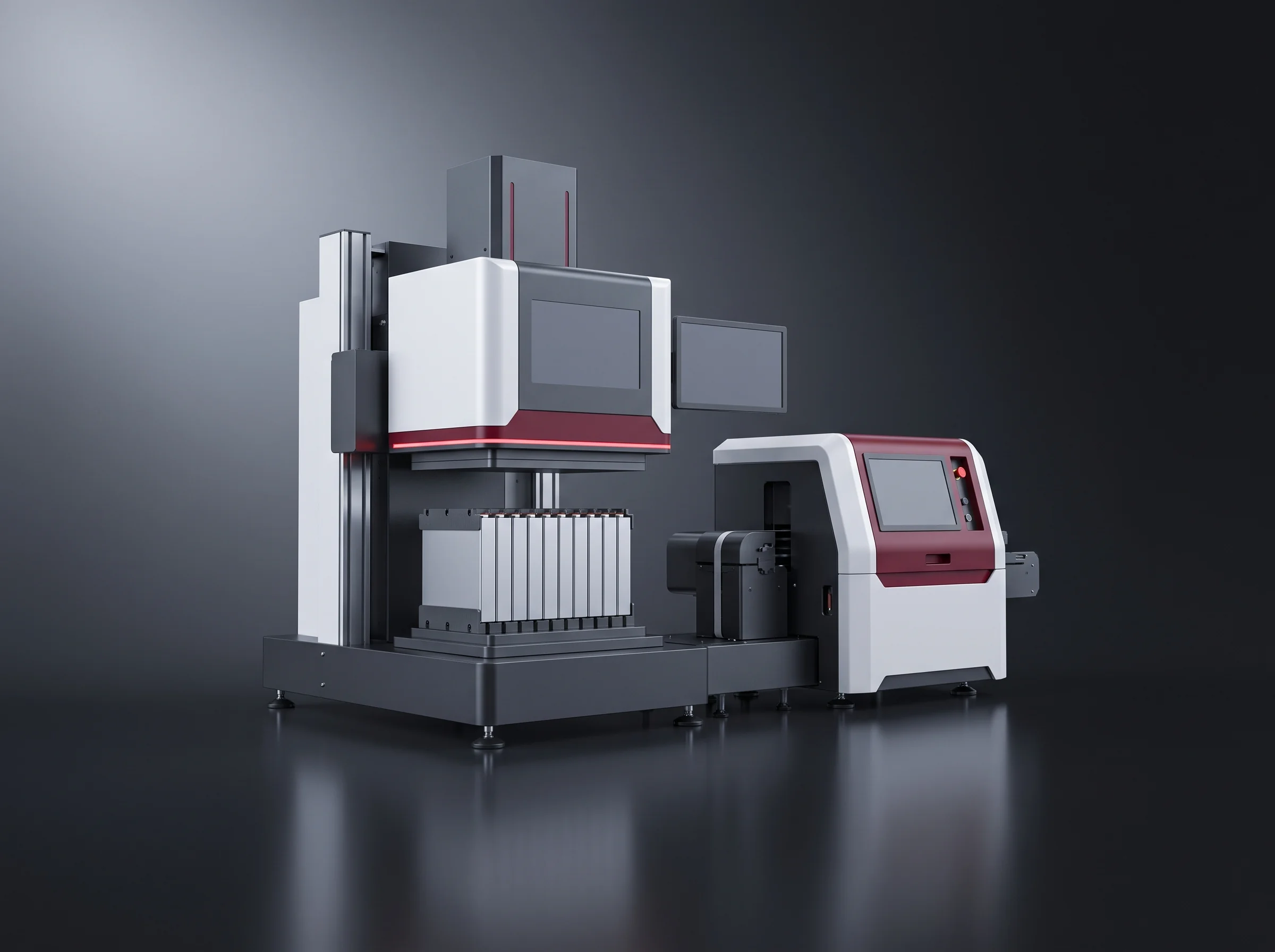
Battery assembly line for module and pack plants, seen along its full run under studio light

Turnkey module & pack lines

Battery Assembly Line Systems for Module and Pack Plants

BatteryLine Pro builds turnkey battery assembly line systems for plants that receive finished cells and ship tested packs. Three line tiers run at 4 to 8, 8, and 12 to 15 PPM, built around 17 module stations and 15 pack stations, laser busbar welding and full EOL testing.

Energy storage pack makers, EV module and pack suppliers, and system integrators moving upstream buy the whole line, one workstation, or a retrofit of one segment.

Cell handlingModule segmentPack segmentLine-off

  • 4 to 15 PPMThree battery assembly line tiers
  • 500 MWh to 2 GWhA year, on the 314 Ah blueprint
  • 17 + 15Module stations and pack stations
  • 99% or betterEquipment-caused yield
  • 1000 N or moreBusbar pull force

The Module & Pack Line

End-to-end production architecture

8 of 32 stations shown Module → Pack

MODULE ASSEMBLY PACK ASSEMBLY THE SEAM Module handover MODULE → PACK Module complete — owned by whoever owns the whole line. 1Cell De-trayLoadingAUTO · ST 01Module segment · 1 of 172Stacking Pressing& BandingAUTO · ST 08Module segment · 8 of 173Busbar LaserWeldingAUTO · ST 13Module segment · 13 of 174Module EOLTestingAUTO · ST 16Module segment · 16 of 175ModuleInsertionMANUAL · ST 04Pack segment · 4 of 156Series BusbarInstallationMANUAL · ST 06Pack segment · 6 of 157Pack EOLTestMANUAL · ST 14Pack segment · 14 of 158PackOffloadMANUAL · ST 15Pack segment · 15 of 15

Everything after the cell arrives

Battery Assembly Line for Storage Packs

A battery assembly line from us covers everything after the cell arrives: cell testing and sorting, module stacking and welding, pack assembly and testing, line-off.

  • Commercial and industrial energy storage pack plants
  • Grid-scale storage integrators
  • Residential storage manufacturers
  • EV module and pack suppliers
  • Plants already running a line that need a station added

Certification

ISO 9001, CE and RoHS.

Answer time

A tier recommendation, layout and station list come back within 24 hours.
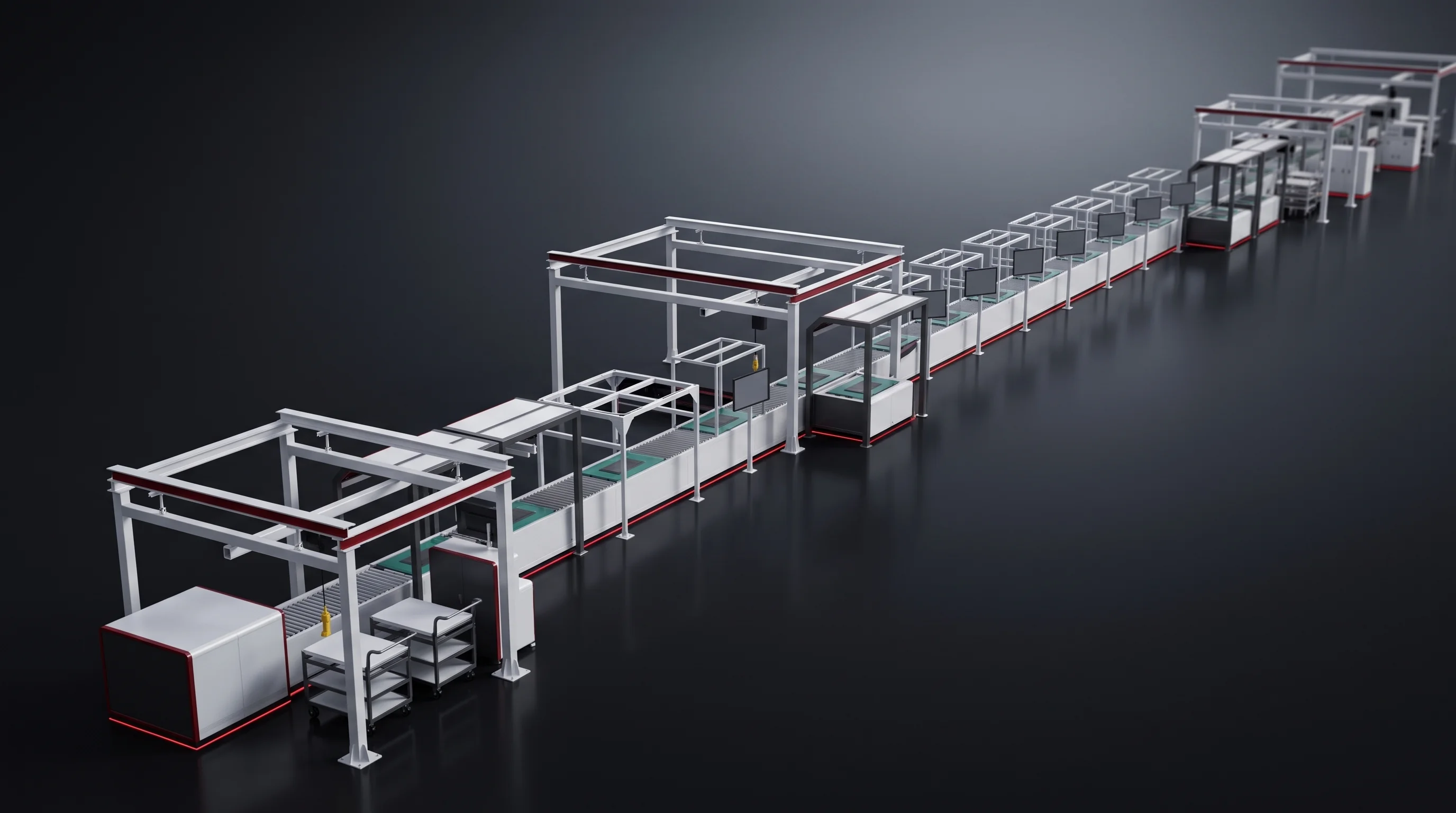
Battery assembly line seen along its full run, from cell handling through to line-off
Three configurations cover 4 to 15 PPM at line lengths of 54 to 56 metres, each laid out against your existing building.

What a turnkey order covers

Turnkey Delivery Package

More on how we are set up is on the company page.

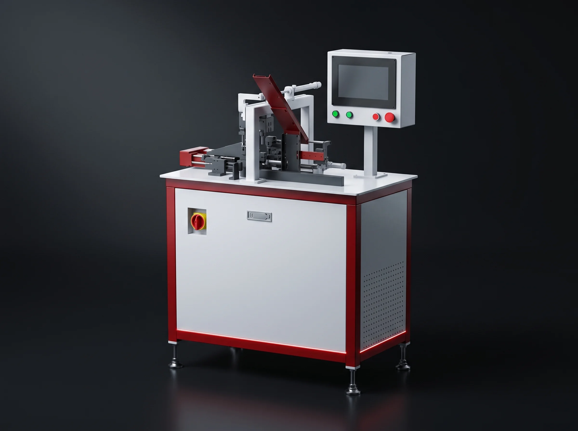
Battery assembly line station drawn to the building it will stand in, with its utility cabinet beside it
The layout comes first, drawn against your building rather than a standard drawing: line run, station spacing, material entry and exit, where operators stand, utility entry points.

Installation and commissioning

Done on your floor by our engineers.

Acceptance

Runs against a written station-by-station criteria set agreed before shipment.

Operator training

Covers operation and maintenance for the people who will run each segment, on the line they will run.

Layout design
Included
Equipment
Included
Acceptance
Included

A complete line

Quoted as one project.

A single workstation

Integrated into a line you already have.

One segment rebuilt

The usual route when a module segment is holding back a pack segment already sized correctly.

Scope boundary
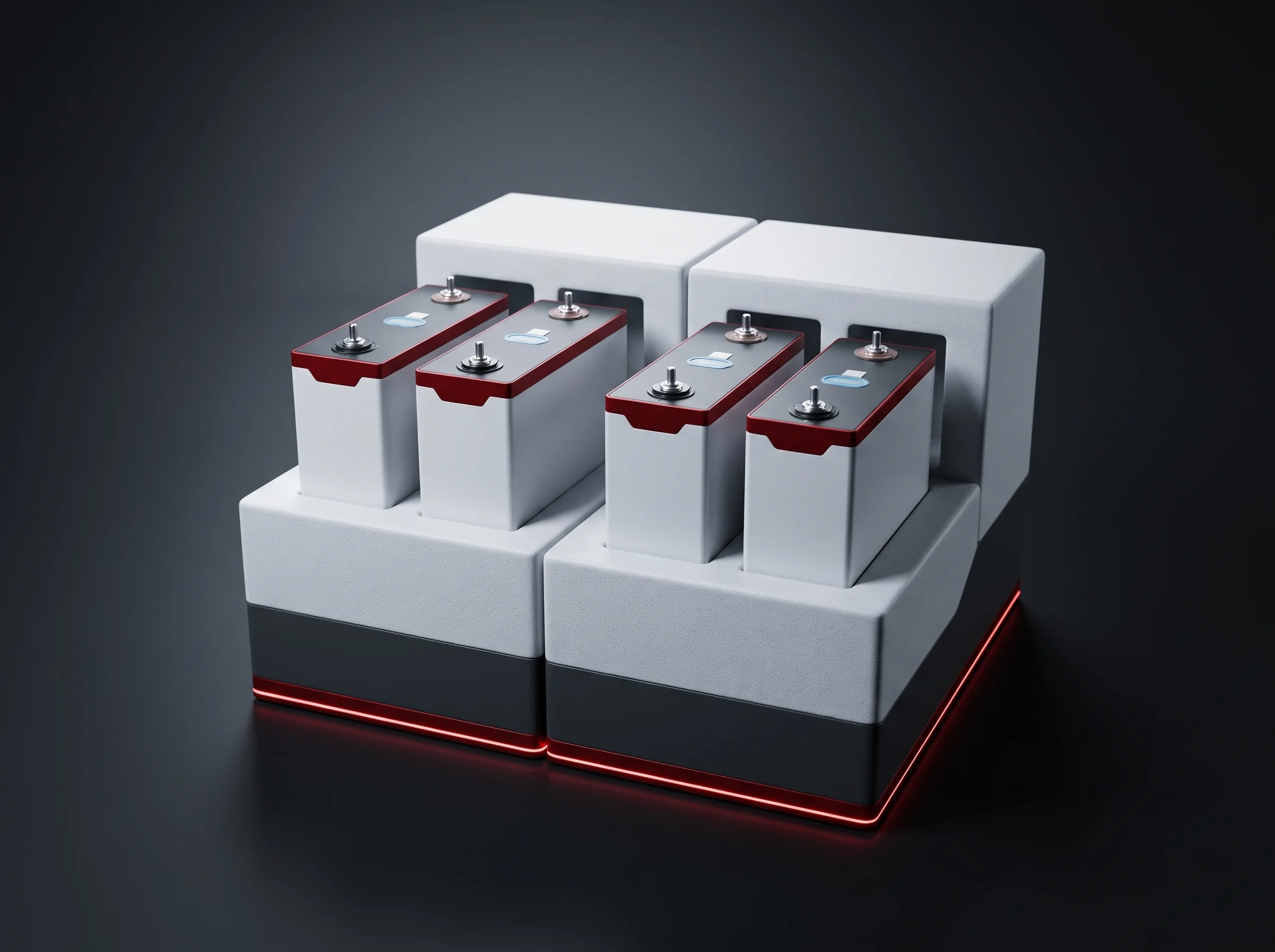
Four Segments After Cell Arrival

Inside our scope

Starts with finished cells on pallets and ends with tested packs at line-off.

Outside what we quote

Cell manufacturing upstream of that point — mixing, coating, calendering, winding, stacking, electrolyte filling and formation.

Prismatic cells arrayed on a tray before the battery assembly line takes them off it

Cell handling

Takes cells off the tray, scans and tests each one, sorts it, and refills the gap a rejected cell leaves.
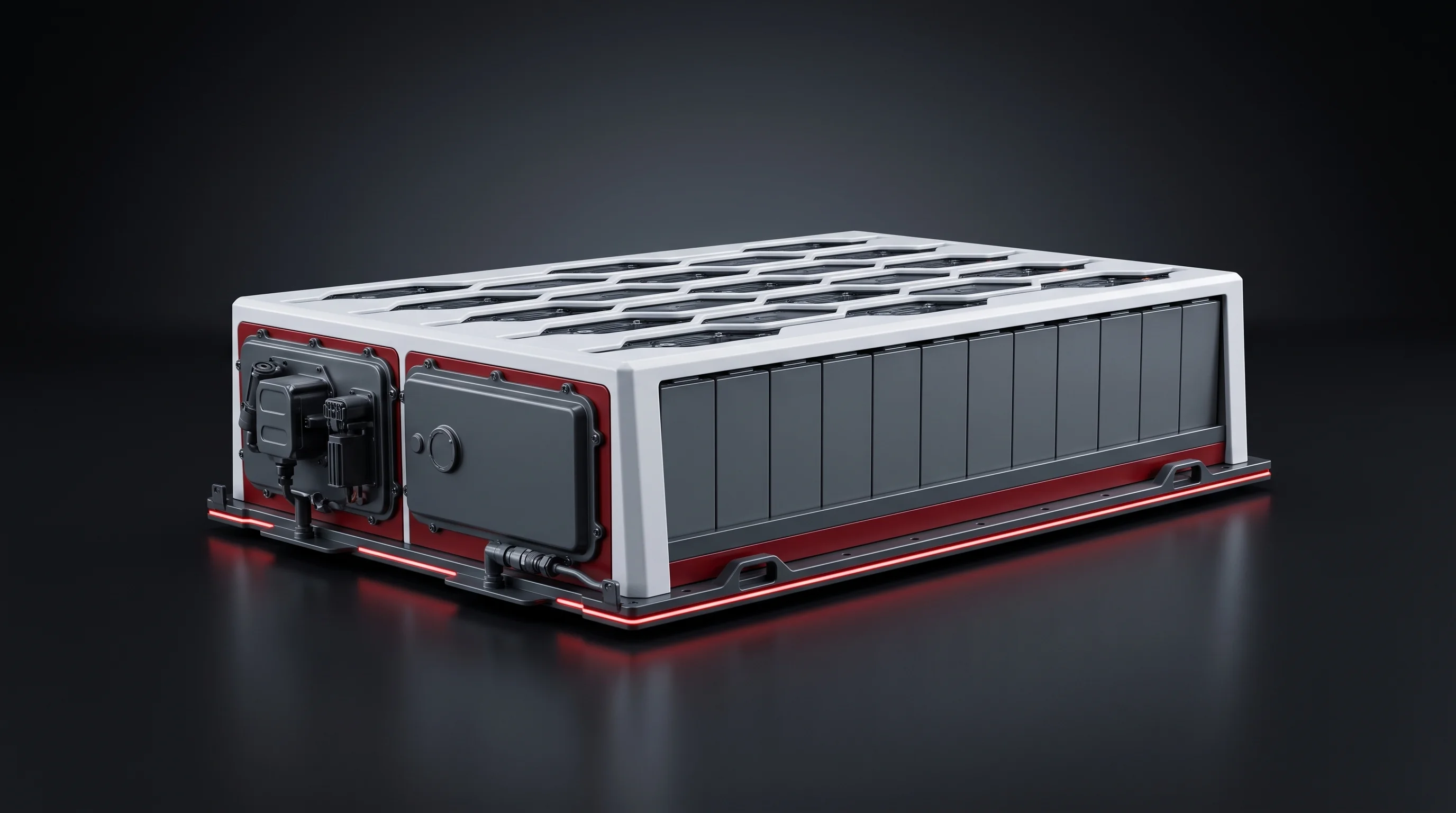
Stations
BLP-UL, BLP-CS
Finished prismatic battery module coming off the module segment

Module segment

Groups, cleans, tapes, stacks, presses, addresses, welds and tests until a finished module comes off.
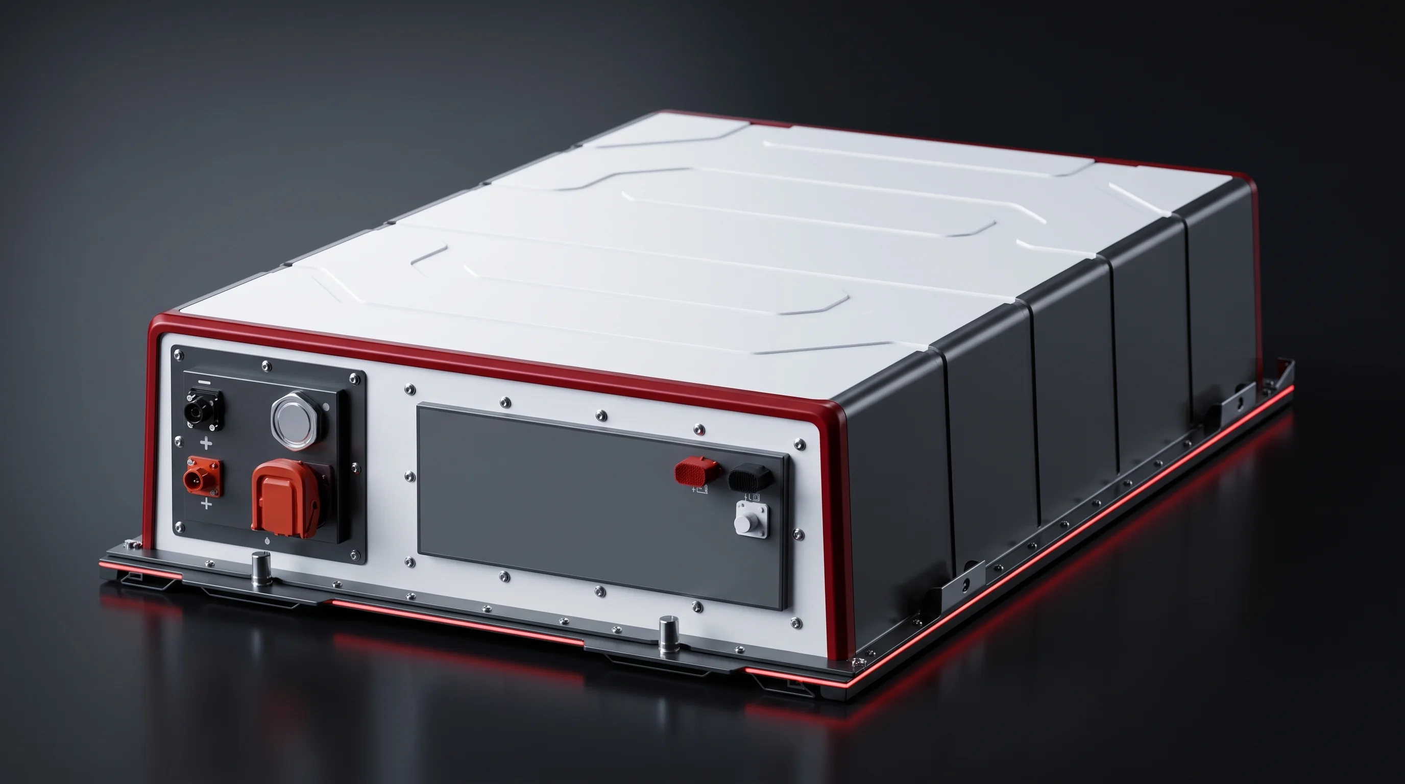
Stations
17
Closed energy storage pack enclosure at the end of the pack segment

Pack segment

Loads the enclosure and cooling plate, glues, inserts and fixes modules, wires the pack, closes it and tests it.
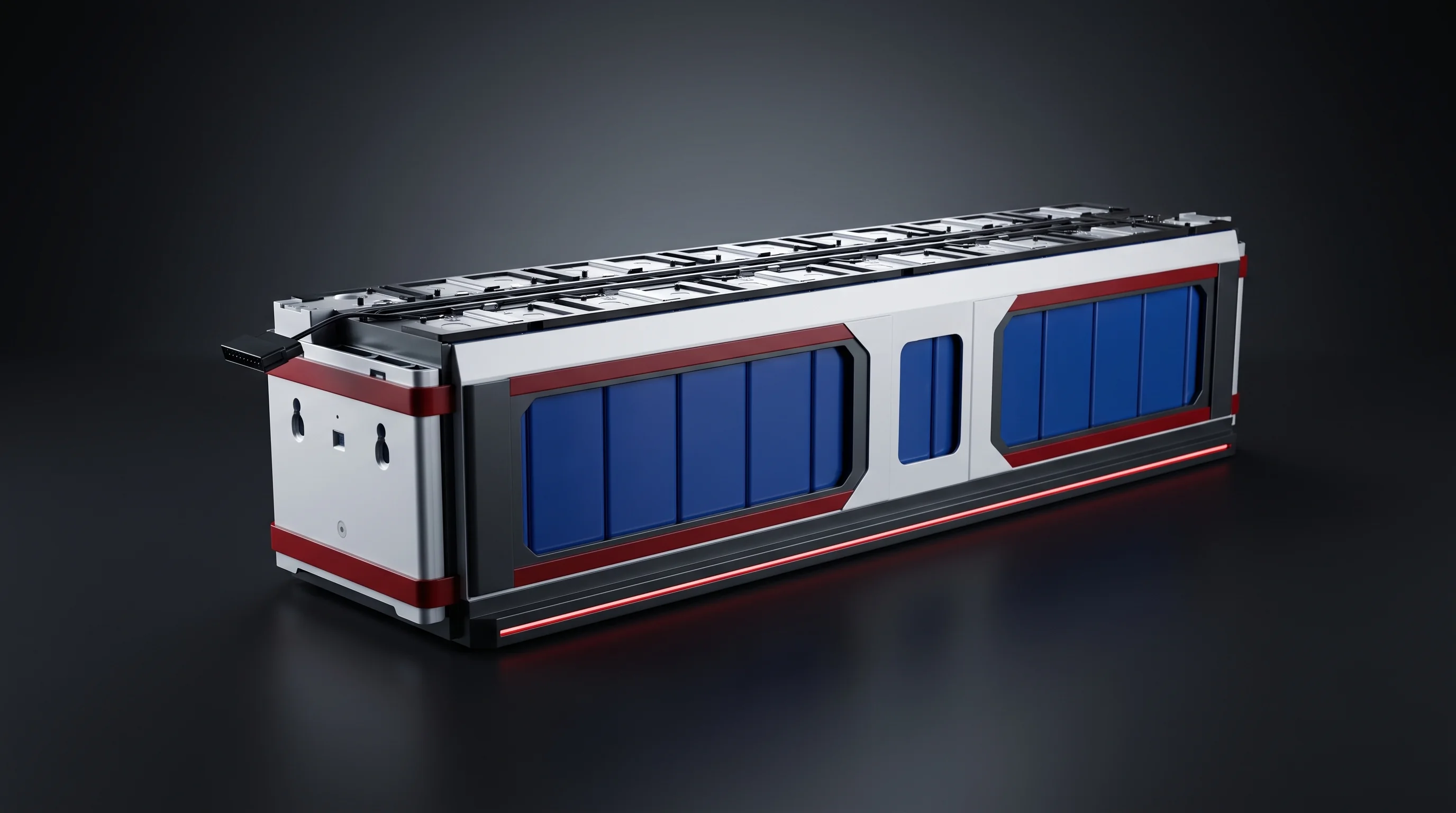
Stations
15
Tested pack released at line-off with its test record attached

Line-off

Releases the pack with its test record attached.

Gate
Pack EOL, station 14

Both segments are documented in full on the battery module assembly line and battery pack assembly line pages.

Our own designs

Nine Workstations Built In House

Nine workstations are our own designs, built in house rather than bought in and relabelled.

The full range sits on the equipment overview.
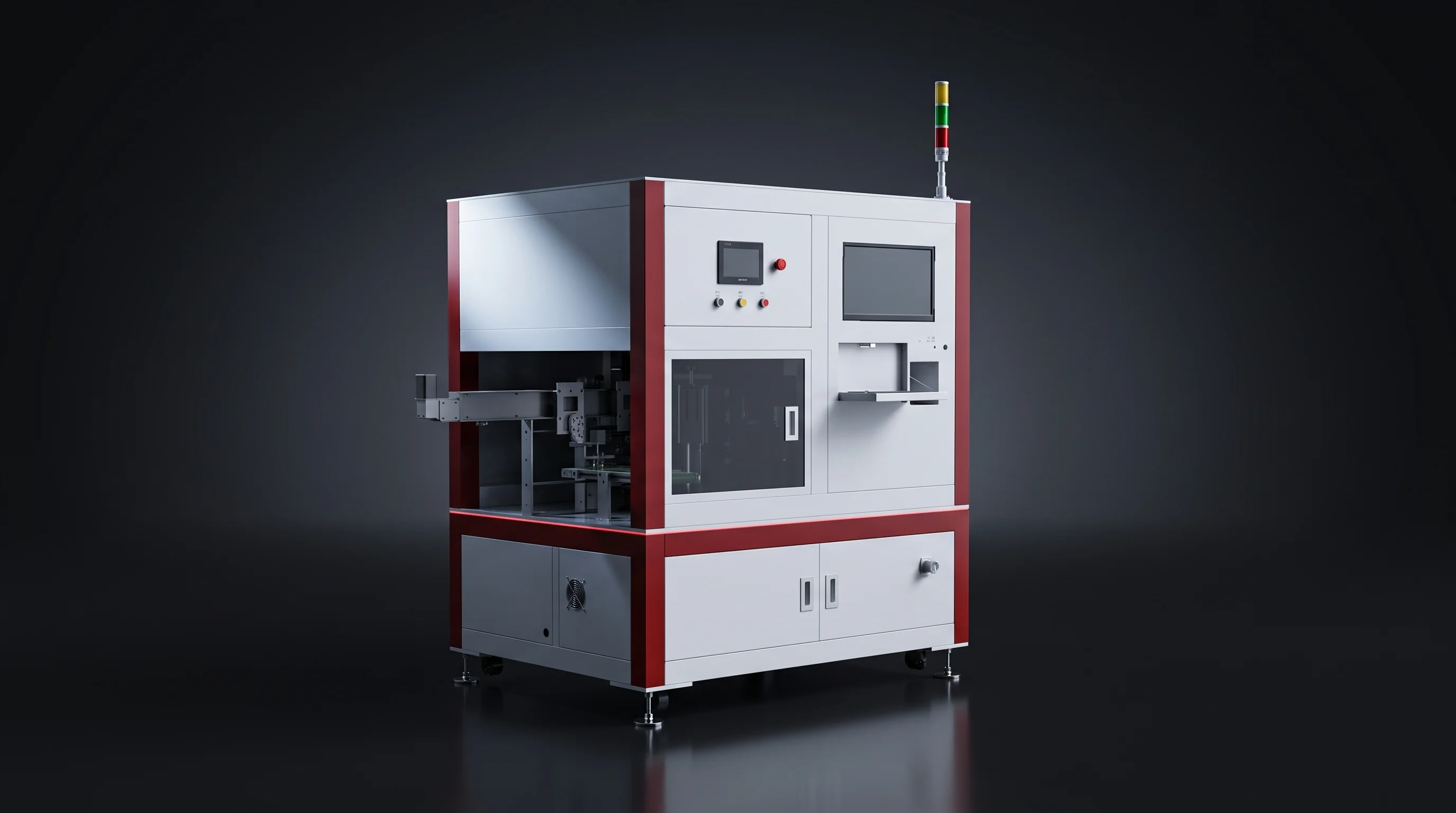
Six-axis robot cell de-tray loading station on a battery assembly line
BLP-UL

Cell de-tray loading

Takes cells off the tray with a six-axis robot and vision.
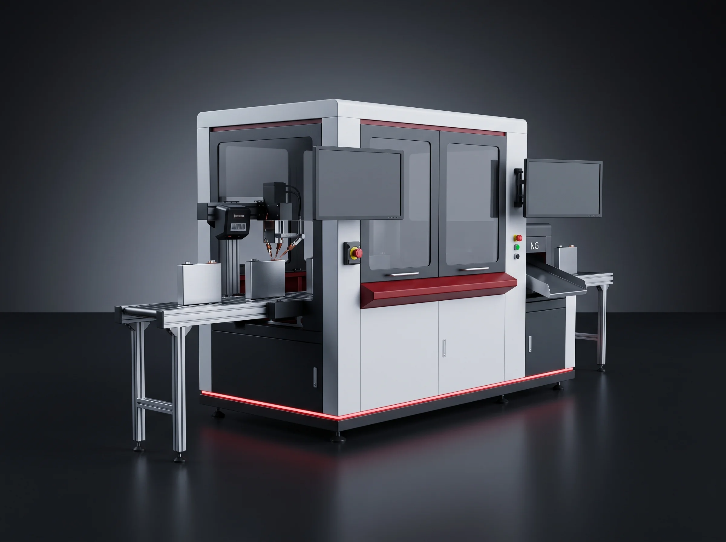
Cell scanning, testing and sorting station on a battery assembly line
BLP-CS

Cell testing and sorting

Scans, tests and sorts them.

Module stacking and pressing station with servo-controlled press
BLP-SP

Stacking and pressing

Stacks and presses modules under servo-controlled force.
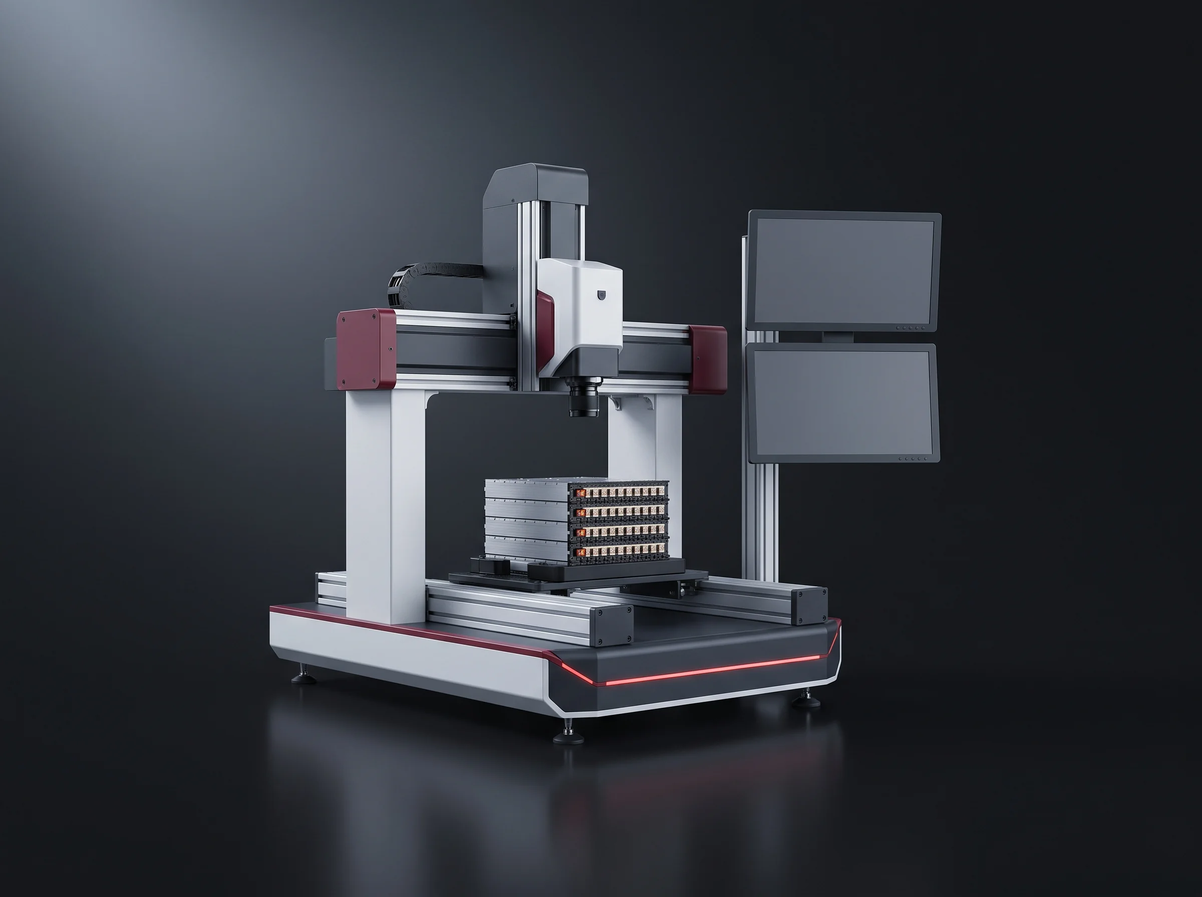
Terminal addressing and polarity check station
BLP-AD

Terminal addressing

Addresses terminals and checks polarity.
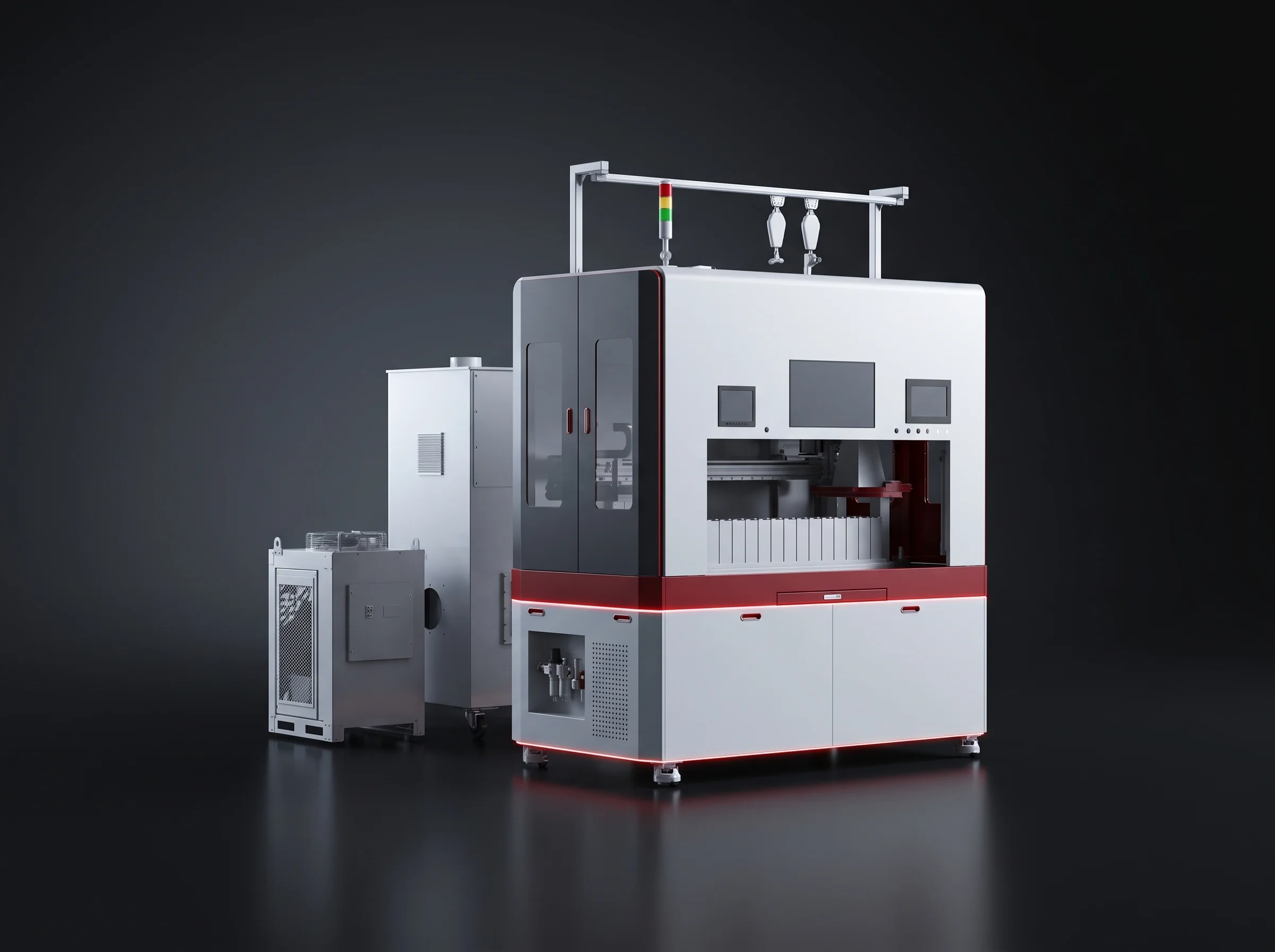
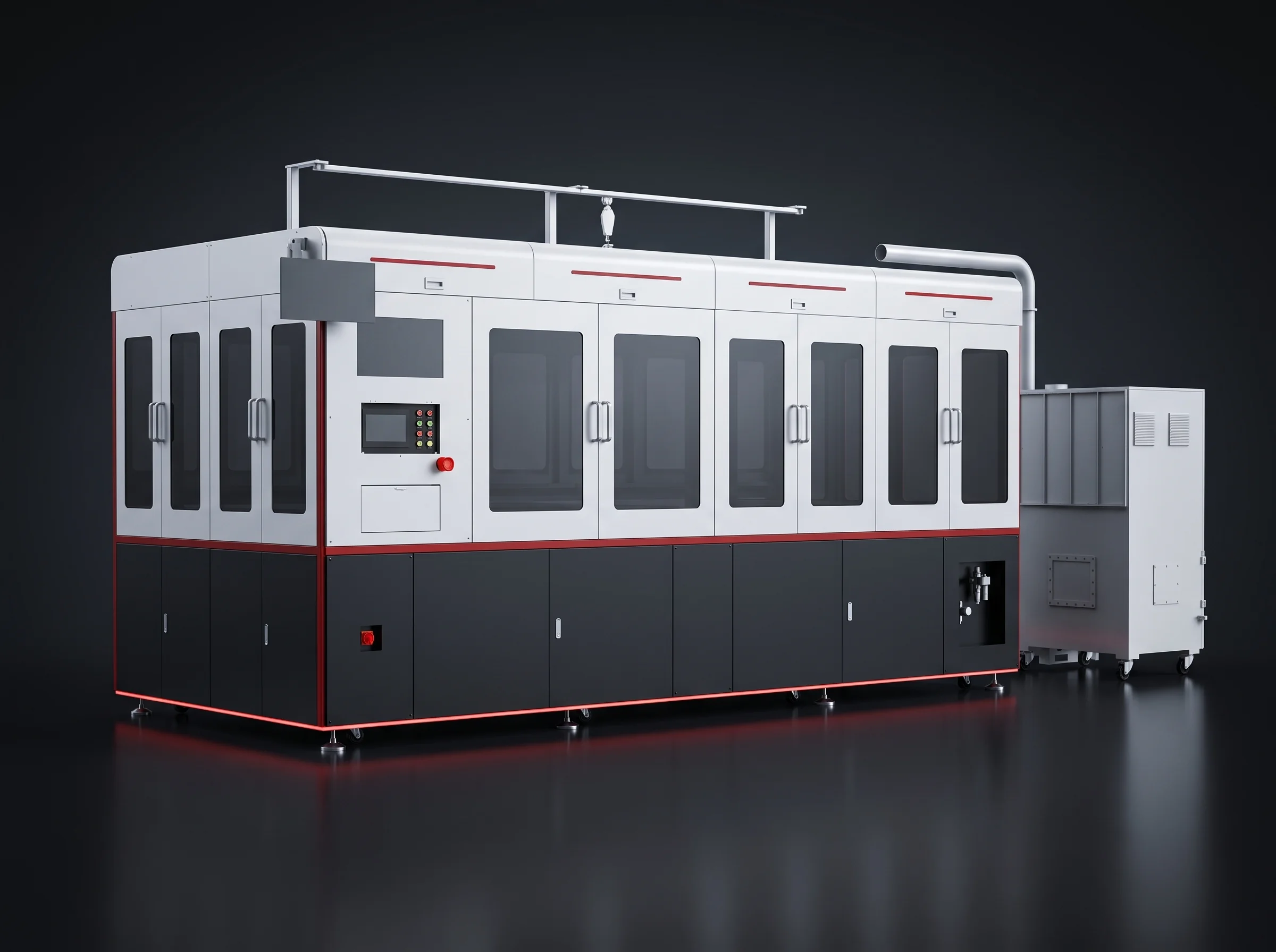
In-line busbar laser welding station with a three-axis gantry and galvo head
BLP-W6

Busbar laser welding

Welds busbars in line with a 6 kW laser.
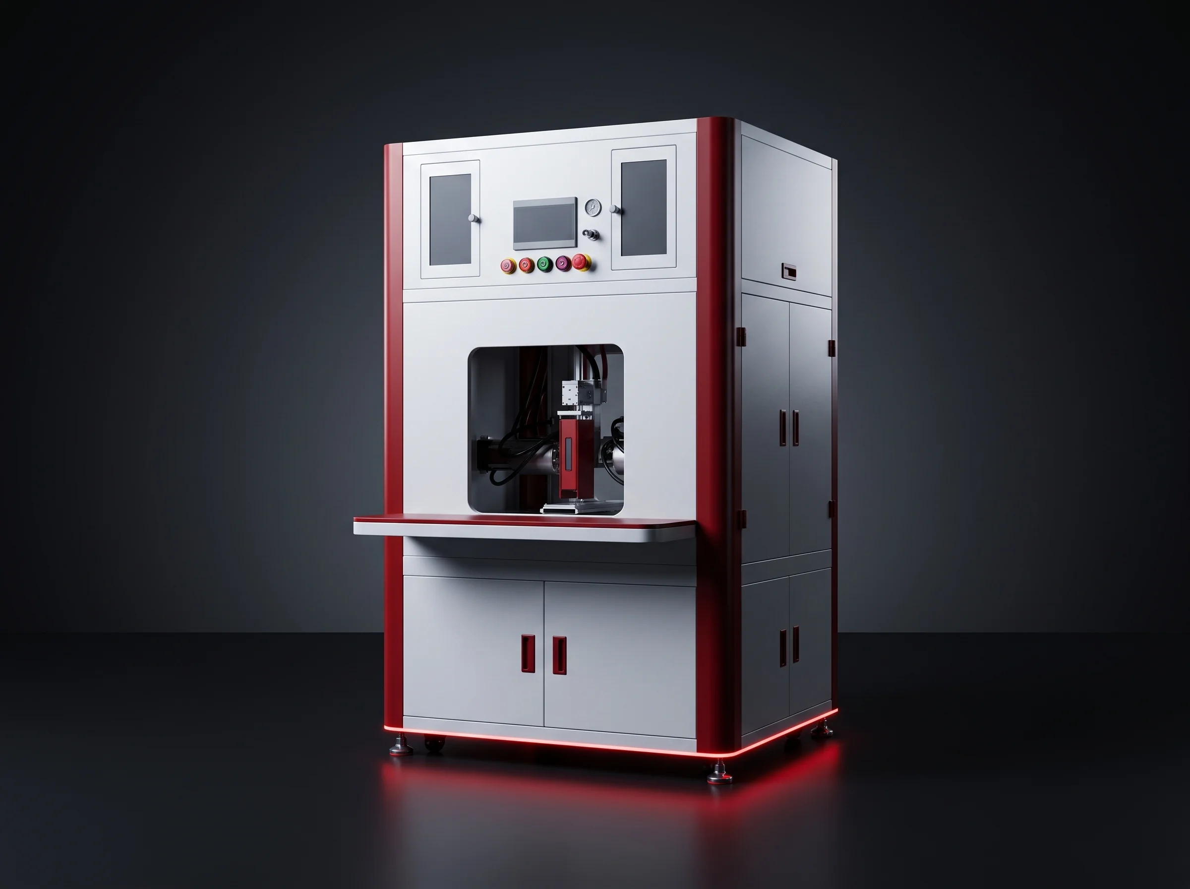
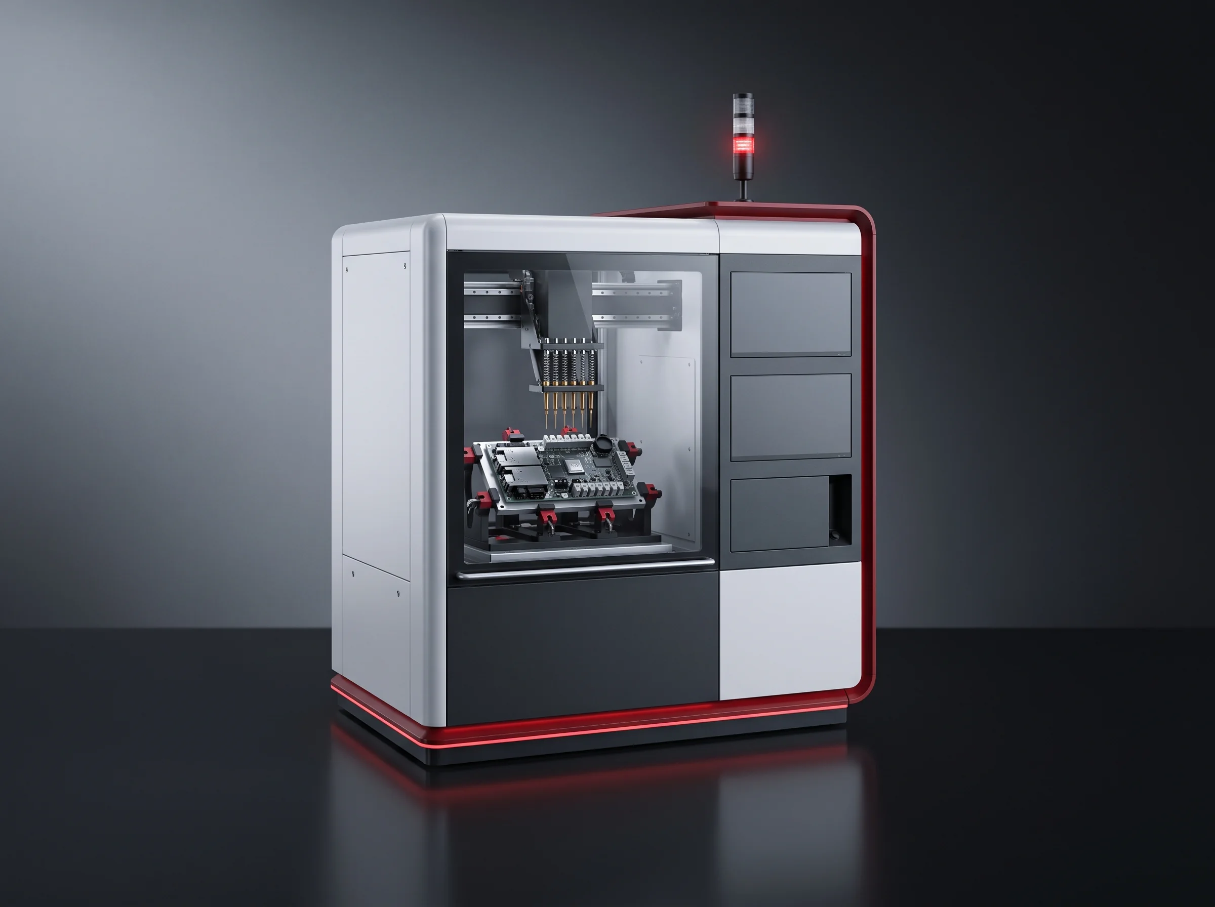
Off-line four-axis gantry laser welding machine beside the battery assembly line
BLP-WG

Off-line gantry welder

For work that does not belong in the takt.
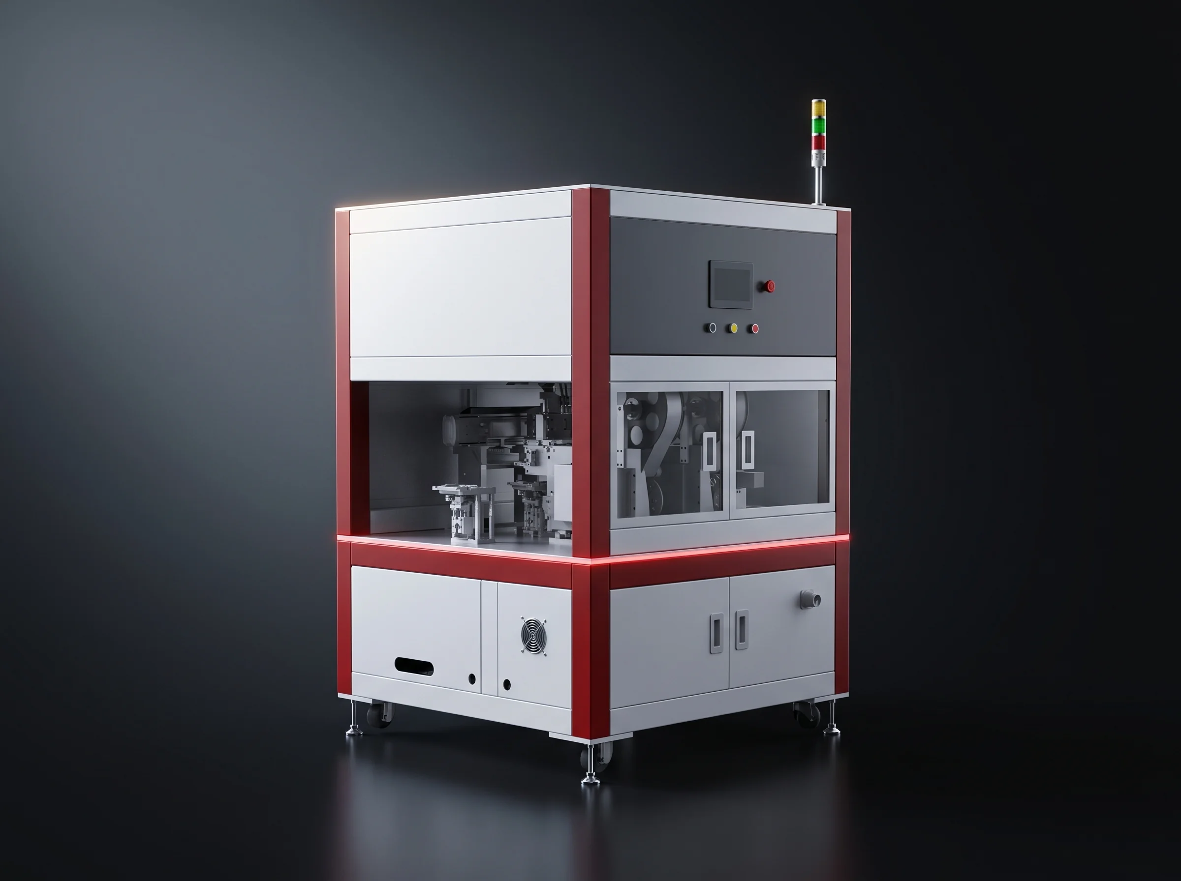
Module end-of-line testing station with its test cabinet
BLP-EOL

Module EOL testing

Runs module end-of-line testing.

Cooling plate and enclosure adhesive dispensing station
BLP-GL

Cooling plate gluing

Dispenses cooling plate and enclosure adhesive.
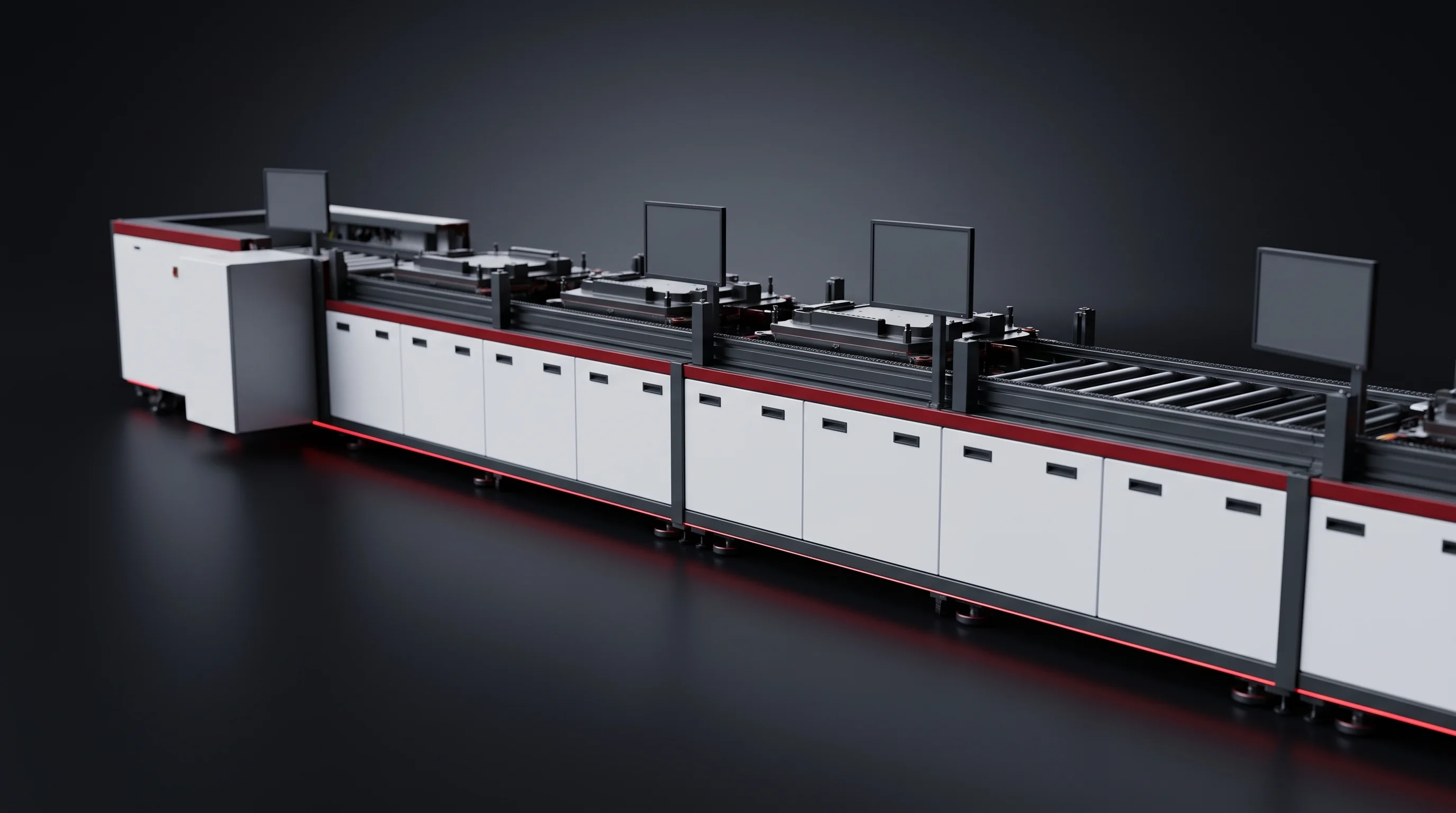
Module conveying section linking stations on the battery assembly line
BLP-CV

Module conveying

Conveys modules between stations.

ISO 9001CERoHSNine stations, our own drawings

Held certifications

Issued against the stations, not the trading company.

Before committing

Ask for the layout drawn to your building and the labelled station list for both segments.

Also on request

The EOL test item list, and the acceptance criteria the line is signed off against.

Takt, footprint, installed power

Three Battery Assembly Line Tiers

The tiers separate on automation level, floor area and installed power. BLP-P8S buys output with people and a narrower building, BLP-P15 with automation and twice the width, and BLP-P8 holds 8 PPM in the smallest footprint.

01
Semi-automatic battery assembly line tier BLP-P8S running 4 to 8 packs per minute

Semi-automatic

BLP-P8S

Output bought with operators and a narrower building, on a 56 by 10 m run.

Takt
4 – 8 PPM
Installed power
200 kW
Annual output
500 MWh – 1 GWh
02
Standard battery assembly line tier BLP-P8 holding 8 packs per minute in the smallest footprint

Standard

BLP-P8

Holds 8 PPM in the smallest footprint of the three, at 55 by 9 m.

Takt
8 PPM
Installed power
up to 250 kW
Bay height
3.5 m
03
High-automation battery assembly line tier BLP-P15 running 12 to 15 packs per minute

High automation

BLP-P15

Output bought with automation and twice the width, on a 54 by 20 m run.

Takt
12 – 15 PPM
Installed power
300 kW
Annual output
1 – 2 GWh
Three battery assembly line tiers compared on takt, footprint and installed power
TierTaktFootprint L x W x HInstalled power
BLP-P8S semi-automatic4 to 8 PPM56 x 10 x 4 m200 kW
BLP-P8 standard8 PPM55 x 9 x 3.5 mup to 250 kW
BLP-P15 high automation12 to 15 PPM54 x 20 x 4 m300 kW

Annual output is counted on the 314 Ah blueprint, 300 working days, 8 hours a day. Any tier can be quoted as a battery pack production line alone where a module segment already exists.

Line utilisation, as we define it

A PPM figure alone does not tell you what a line ships in a year. Two numbers sit under it, both written into the contract before the line is built.

  • Line utilisation is time utilisation multiplied by performance utilisation multiplied by first-pass yield.
  • First-pass yield is input quantity minus NG units divided by input quantity.
  • Tier selection against a target output is worked through on the capacity planning page.

99%

or better, counted on equipment causes alone, with human factors excluded from the count.

Every station, named

Battery Module Assembly Line Sequence

Detail is on the module line and pack line pages.
17 Module segment stations

  1. Cell tray unloading
  2. Scanning, OCV testing and sorting
  3. NG rejection and OK refill
  4. Cell flipping and grouping
  5. Large-face plasma cleaning
  6. Cell taping
  7. End plate and insulation sheet handling
  8. Module stacking
  9. Pressing, shaping and steel band strapping
  10. Polarity and insulation testing
  11. Terminal addressing with laser cleaning
  12. Busbar and CCS assembly installation
  13. Busbar laser welding
  14. Post-weld cleaning and inspection
  15. Manual re-inspection and communication testing
  16. Module EOL testing
  17. Module line-off
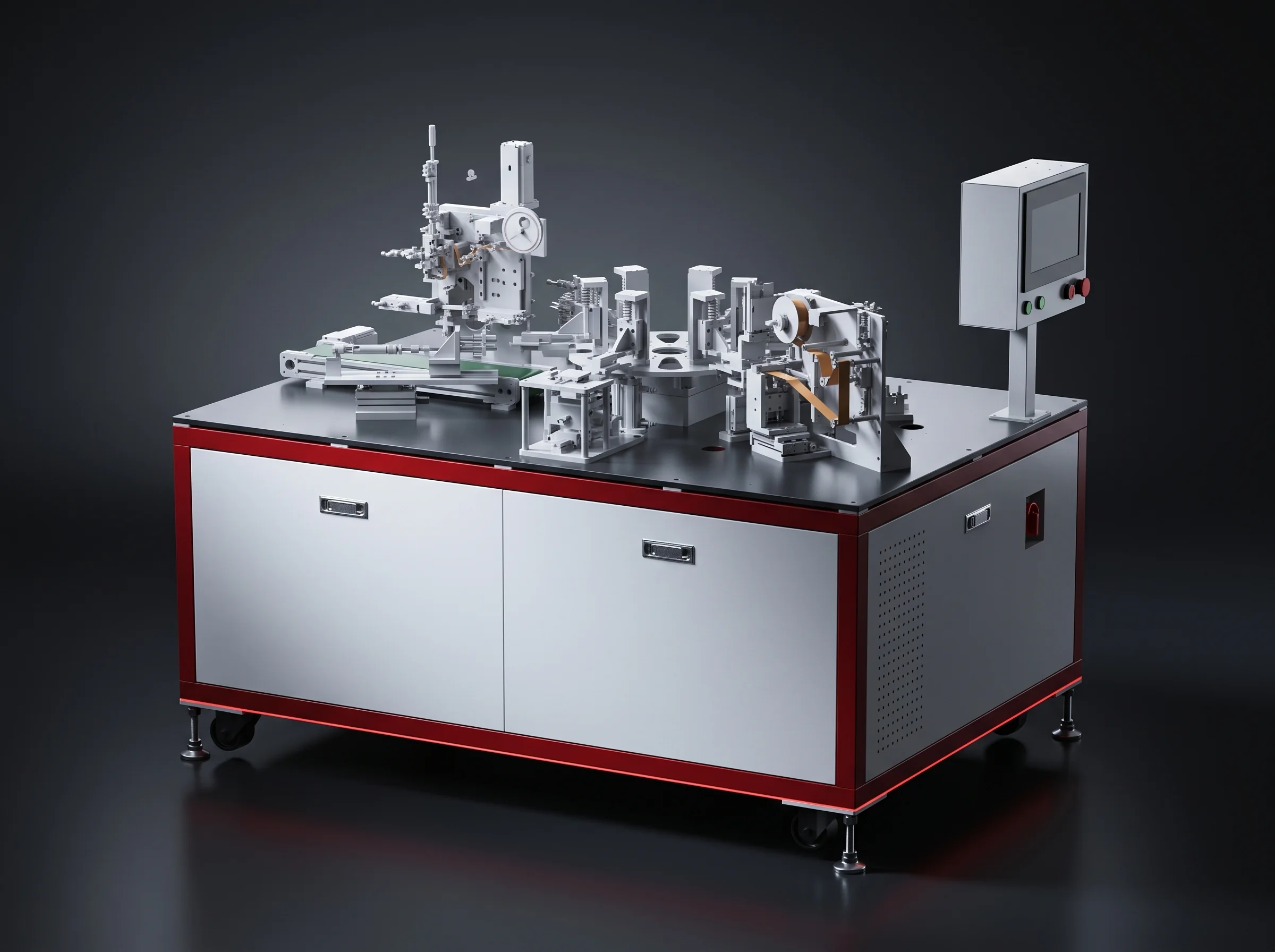
Cell taping station, station six of the module segment

15 Pack segment stations

  1. Enclosure and cooling plate loading and cleaning
  2. Cooling plate air-tightness testing
  3. Enclosure floor gluing
  4. Module insertion
  5. Module fixing
  6. Series copper busbar installation
  7. BMS installation
  8. MSD and high and low voltage connector installation
  9. Harness dressing
  10. Upper cover installation
  11. Upper cover tightening
  12. Front panel installation
  13. Whole-pack air-tightness testing
  14. Pack EOL testing
  15. Pack line-off
Module line-off Module insertion Handover, one takt
Module drawn in section, showing the stack the module segment builds

Seventeen and fifteen are the numbers we quote against, and every station in both lists is labelled AUTO, SEMI-AUTO or MANUAL in the layout package before you sign.

Where the packs go

Storage and EV Pack Applications

Storage-specific line configuration is covered on the energy storage pack line page.

Modular commercial and industrial storage pack built on a battery assembly line

Commercial and industrial storage

Our first market. Pack count per project is high enough that takt and headcount decide the case.

Capacity
100 kWh – 10 MWh
Voltage
400 – 800 V
Architecture
Modular, independent PCS
Grid-scale storage line built from the same prismatic modules

Grid-scale storage

Second. Containerised with central PCS, liquid-cooled, built from the same prismatic modules.
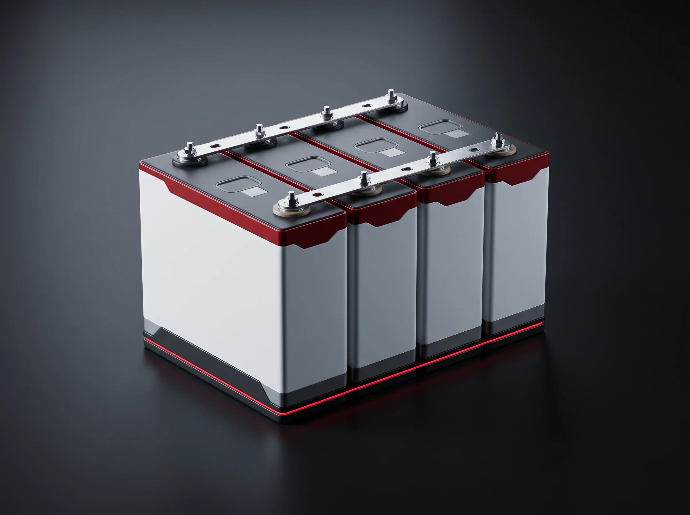
Capacity
10 MWh – 1 GWh+
Voltage
10 kV and up
Cooling
Liquid
Prismatic cell of the family used for residential storage units on the semi-automatic tier

Residential storage

Third. Usually air-cooled and built on the semi-automatic tier.
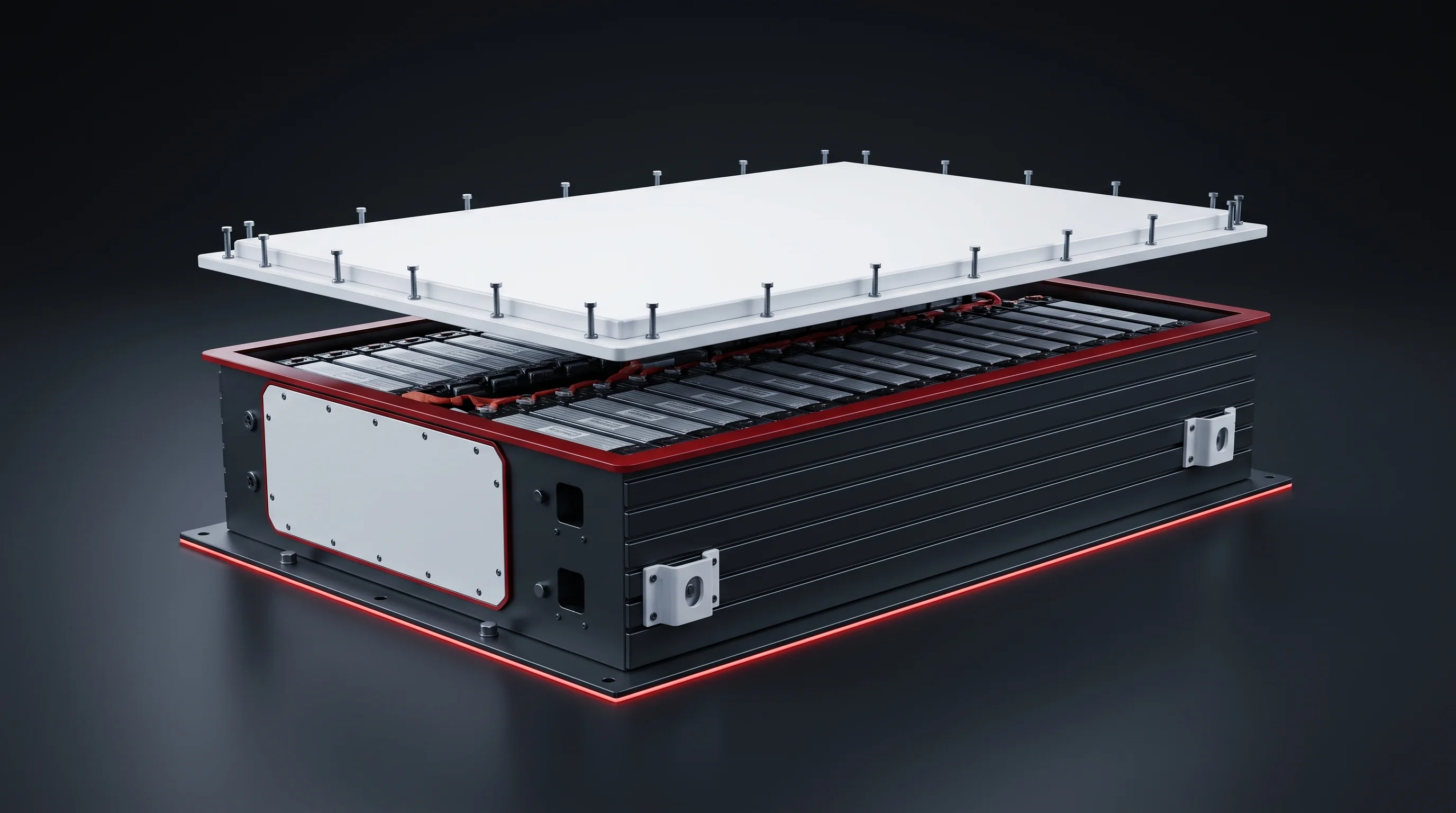
Capacity
5 – 30 kWh
Voltage
48, 120 or 240 V
Architecture
Inverter and battery unit
EV pack enclosure and lid drawn to a customer-fixed pack drawing

EV module and pack suppliers

Fourth. Arriving with a pack drawing fixed by their customer and a takt fixed by the vehicle line.

Drawing
Customer-fixed
Takt
Vehicle-line fixed
Scope
Module and pack

What the roster will cost you

Line Headcount by Segment

Every quotation for a battery assembly line carries a headcount, and it sets your shift roster and labour cost long after the equipment is paid for. Ours, per segment:

TierCell handlingModule weldingPack assembly
BLP-P8S4412 – 14
BLP-P154312 – 14

The high-automation tier takes one person out of the module segment and none out of the pack segment.

Battery assembly line seen along its run, with the manual pack segment at the far end
That is the honest shape of a line.
01
Cell handling and the module segment carry the automatic stations: tray unloading, scanning and sorting, stacking and pressing, terminal addressing, busbar welding, module EOL.
02
The pack segment is predominantly manual on every tier, and on BLP-P8 its one automatic station is enclosure floor gluing.
03
That work is:
  • Module insertion and fixing
  • Series copper busbar installation
  • BMS installation
  • MSD and connector installation
  • Harness dressing
  • Cover installation and tightening
  • Front panel installation
04
Each changes shape with the pack variant: a different harness route, bracket or connector position. Automating them means dedicated tooling per variant, written off the day that variant is superseded. Twelve to fourteen people absorb a variant change on the day the drawing lands.

Multiply the pack segment headcount by your shift pattern and local labour rate, add it to the equipment figure, and compare that against a quotation calling the same pack segment fully automatic. The gap is usually wider than the gap between the two equipment prices, and it recurs every month.

Busbar laser welding station BLP-W6, station 13 of the module segment on the battery assembly line
A three-axis gantry carries a galvo head over the module, the module stays on its fixture, and the head travels to each joint.

Station 13 of the module segment

Busbar Laser Welding Station BLP-W6

A 6 kW laser lays each busbar-to-terminal joint at 50 to 100 mm/s, and one station handles single-row and double-row modules without a mechanical change.

≥1.0 mmPenetration
≥1.5 mmBead width
≥1000 NPull force

Three figures define an accepted joint.

Sample

Pull testing destroys the joint, so it can never run on a production module. Parameters are set on sample joints made from your own busbar and terminal material.

Lock

Samples are pulled until the 1000 N floor is met with margin, and the power, speed, focus and beam pattern that produced them are locked as the recipe for that busbar geometry.

Call

The operator does not hold the recipe. It is stored per busbar geometry and called by the part that arrives, and the station will not run a geometry with no locked recipe.

Read

Every production joint is checked on the two measurements that survive the part, penetration and bead width, read at station 14, post-weld cleaning and inspection.
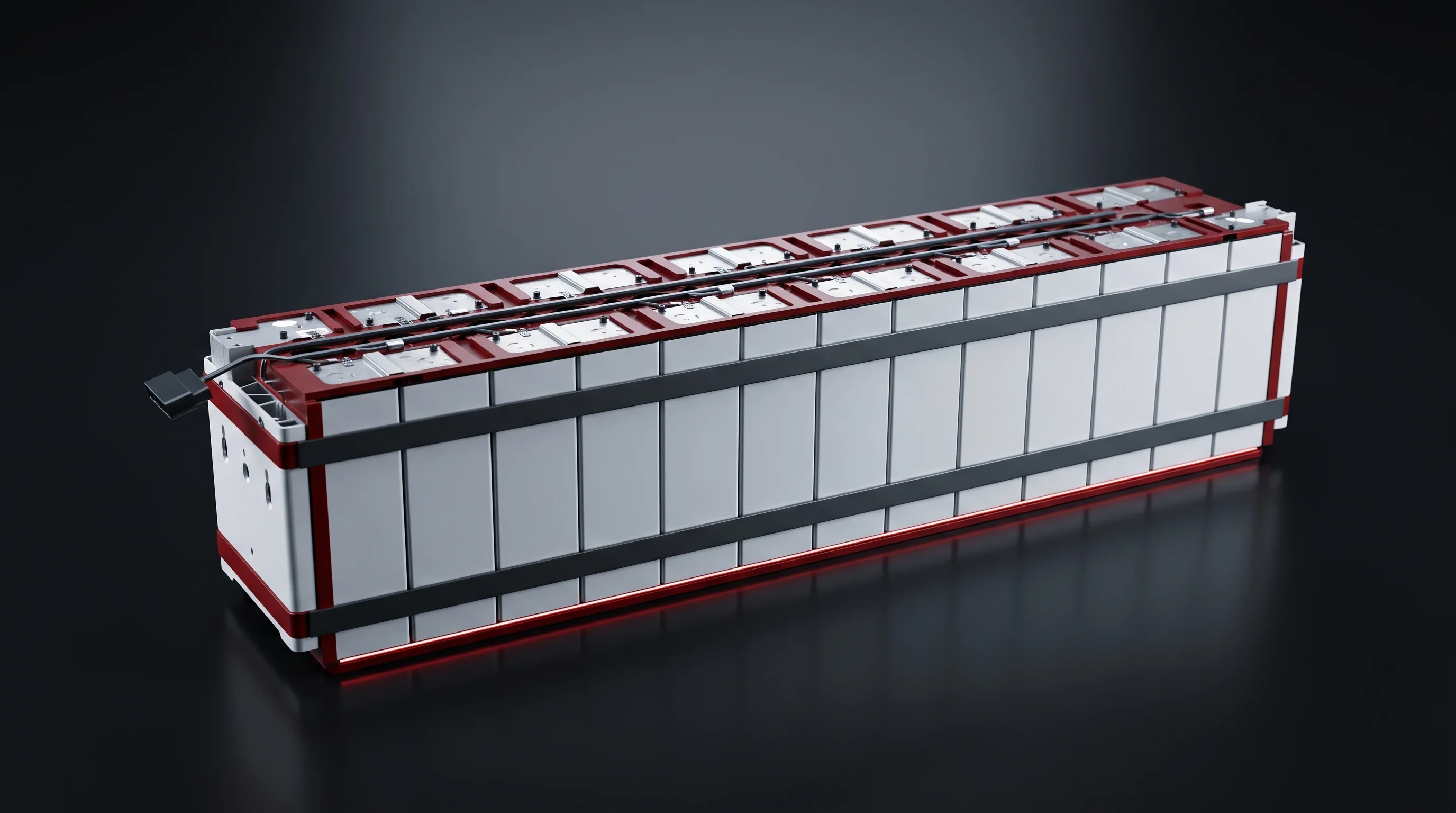
A joint outside penetration or width

  • Marked at station 14; the module leaves the flow before manual re-inspection at station 15 and module EOL at station 16.
  • Rework is a decision on your side of the line, because a re-welded joint no longer matches the sample the recipe was proved against.
  • The station records what it found, so the module is judged on a measurement.

You receive

  • The locked recipe for each busbar geometry
  • The sample pull-test results it was proved against
  • The penetration and width record for every production joint
Welded busbars across the terminals of a finished module on the battery assembly line
This station carries more of the argument than any other because it is the only station in the module segment whose output cannot be undone. Everything before it can be unstacked, re-taped or re-sorted.

A burn-through writes off thirteen cells bought with your money, and a cold joint leaves the plant and shows up as rising resistance months later.

Detail is on the busbar welding station page.

Two gates, one record

Cell Sorting and End-of-Line Testing

Two gates carry everything between them: cells are graded before a module is stacked, modules and packs are tested before they leave, and both write to the same record.

Detail is on the cell testing and sorting station and pack EOL testing pages.

BLP-UL · BLP-CS

Incoming gate — scan, test and sort

Cell de-tray loading and sorting head at the incoming gate of the battery assembly line

BLP-UL takes cells off the incoming tray with a six-axis robot carrying vision, and palletises the empty foam trays without an operator. BLP-CS scans, tests and sorts every cell against the criteria you set.

Robot payload / reach
220 kg / 2650 mm+
Positioning
0.06 mm, 5 cells a pick
Scan success
99.9% or better
Voltage accuracy
±0.01% rdg + 3 dgt
Resistance accuracy
±0.5% rdg + 10 dgt

Rejecting a cell is the simple half. The gap it leaves is the half that stops a line, because a module cannot be stacked one cell short and downstream stations are indexed on a full group.

BLP-CS rejects the NG cell and refills the position from the sorted buffer in the same cycle, so the group leaving station 3 is complete and matched.

BLP-EOL

Outgoing gate — module and pack EOL testing

Closed pack going into whole-pack air-tightness and pack end-of-line testing

Module end-of-line testing runs at station 16 of the module segment. Four items, each with a pass criterion set before the line runs and recorded per module.

BLP-EOL test itemConditionCriterion
InsulationDC 1000 V500 MegaOhm floor
HipotDC 2800 VLeakage 10 mA or less
Total voltage and resistancePer moduleRecorded
ContinuityPer moduleRecorded
Station 2Cooling plate air-tightness, on its own
Station 13Whole-pack air-tightness
Station 14Pack EOL testing

The cooling plate is tested before a module goes into the enclosure, because a leak found after insertion costs the modules as well as the plate.

Every unit carries a test record from module EOL through to pack line-off, and that record is what your own customer will ask for.

Send Your Cell Specification

A tier recommendation, a layout and a station list come back within 24 hours.

Cell datasheet Module configuration Pack drawing Target takt Floor plan

Blueprint parts and their limits

Cell and Module Compatibility Envelope

A cell that stays inside the envelope is a tooling change rather than a line change, and that distinction decides what happens when your cell supplier moves you to the next format.

The full picture is on the cell compatibility and changeover page.

Blueprint cell314 Ah prismatic, 72 x 173 x 207 mmThickness by width by height, held to plus or minus 0.5 mm on each axis. The semi-automatic and high-automation tiers are also blueprinted on the 280 Ah cell of the same family, quoted there as 71.3 x 174 x 207 mm.
Blueprint module1P13S, 978.4 x 178.9 x 205 mm100 kg or less.
Blueprint pack1P52S, 1152 x 810 x 243 mm400 kg or less.

Each tier carries an envelope

EnvelopeBLP-P8S and BLP-P15BLP-P8
Cell100 – 220 wide, 100 – 220 high, 20 – 80 thick
Module400 – 1200 x 100 – 300 x 100 – 250 mm300 – 1000 x 150 – 370 x 100 – 240 mm
Pack600 – 1200 x 300 – 800 x 100 – 250 mm

Compatibility with 587 Ah large-format cells is on our roadmap, not a capability of these tiers today.
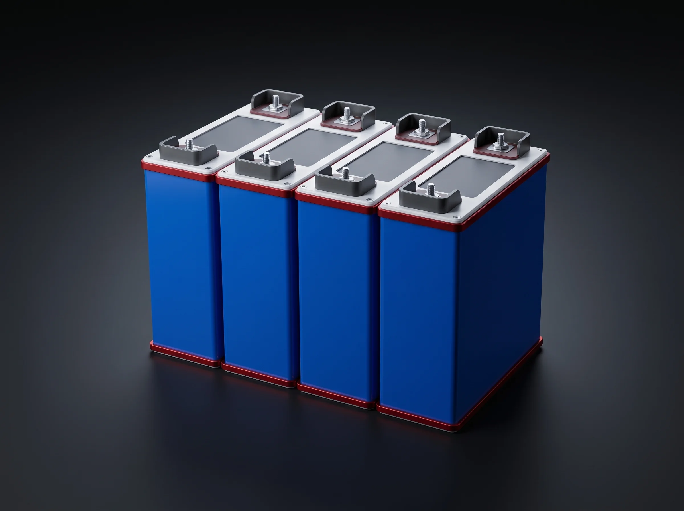
Prismatic cell seen from the terminal face, held to the blueprint tolerance on each axis
Cell envelope, blueprint 314 Ah prismatic
Pack enclosure and lid drawn to the blueprint pack dimensions
Pack envelope, blueprint 1P52S

Changeover tooling inside the envelope

Four things change with the part

  • BLP-ULThe gripper and tray pattern, because the pick geometry follows the cell face.
  • BLP-SPThe stacking and pressing fixture, since press length is set for the module.
  • BLP-ADThe addressing programme and fixture, because terminal positions move.
  • BLP-CVThe stop and lift positions, which locate the module for the station that follows.

Four things do not change

  • ConveyorThe conveyor run.
  • BLP-W6The laser source and gantry.
  • InstrumentsThe test instruments in BLP-CS and BLP-EOL.
  • BLP-GLThe metering system.

A format change inside the envelope is therefore a set of fixtures and programmes, quoted as such — not a new line, and not a rebuild of the conveyor run.

Stations 8, 9 and 11 of the module segment

Stacking, Gluing and Addressing Stations

Three stations decide whether a module holds its dimension, seals, and presents its terminals where the laser expects them. Each writes a curve the next station reads.

Full data sheets on the stacking and pressing, cooling plate gluing and terminal addressing pages.
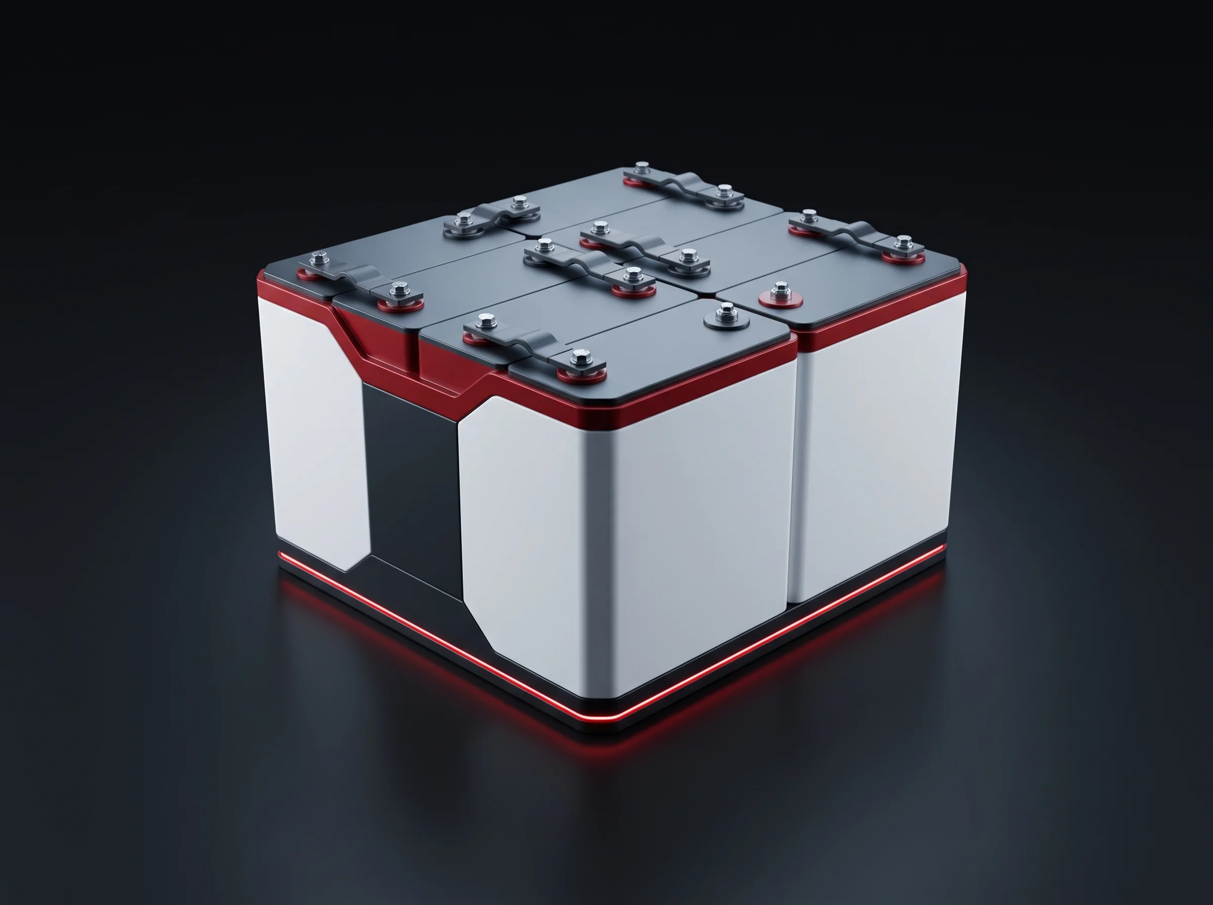
Grouped cells arriving at the module stacking and pressing station of the battery assembly line
BLP-SP

Stacking and pressing

Stacks the grouped cells with their end plates and insulation sheets, presses the stack, and applies the steel bands that hold it.

Press force
0 – 8000 N servo
Module length
300 – 1100 mm
Sensor reading
Full stroke
  • The 0 to 8000 N range is what the machine can apply; the setpoint inside it belongs to your cell and end plate, fixed at commissioning.
  • The sensor reads through the stroke, so every module leaves with a force curve, not a single end-of-stroke number.
Adhesive dispensing station for cooling plate and enclosure floor on the pack segment
BLP-GL

Cooling plate gluing

Dispenses adhesive onto the cooling plate and enclosure floor under dual-servo metering, with camera positioning on every bead.

Camera positioning
0.2 mm
Bead path
2 mm
Dispensed volume
Metered to 5%
  • Volume is controlled; pressure proves it. A blocked nozzle or an air pocket in the cartridge shows up in the pressure curve while the part is still on the station, long before an air-tightness test.
  • Curves upload to your MES over PROFINET, so the record travels with the pack.
Module terminals located and polarity read before the busbars go on
BLP-AD

Terminal addressing

Finds every terminal and confirms its polarity before the busbars go on, with one vision set doing both jobs.

Speed
200 – 300 mm/s
Addressing
0.2 mm or better
Vision
Locate and polarity
  • An address off by more than the tolerance puts the weld off the terminal.
  • A polarity read wrong puts a short into a module about to be welded shut — cheap here, expensive one station later.
PROFINET to MESDual-servo meteringServo press, full-stroke curveSingle vision set

All three are quoted as single stations as readily as they are quoted inside a line, because each one is the station a plant discovers it needs after the line is already running — a press that will not hold the module dimension, a bead that fails air-tightness, an address that walks off the terminal.

BLP-CV

Module conveying between them

Moves modules and fixtures between stations, with modular stop and lift units that locate the part for the station that follows.

Load
200 kg or more
Speed
up to 20 m/min
Guarding
Both sides panelled
  • BLP-CV also appears at the handover into the pack segment, carrying modules and fixtures to that point; it does not convey finished packs.
  • Detail is on the conveyor system page.
Panelled module conveying section moving modules and fixtures between stations
Stop and lift units are modular, so a format change moves positions rather than replacing the run.

Measured under the lowest obstruction

Building, Floor Load and Utilities

Your building is an input to the layout, and the one most often measured wrong.

  • Clear height is measured under the lowest obstruction over the line run rather than to the roof.
  • A ceiling service layer of cable tray, sprinkler, ducting and crane rail commonly takes 300 to 500 mm, so a 4 m beam soffit can leave 3.6 m usable.
  • Floor loading is 800 kg per square metre or more.

Power

Three-phase five-wire 380 V plus or minus 5% at 50 Hz.

Compressed air and shielding gas

Air at 0.5 to 0.7 MPa; nitrogen shielding gas at 0.5 MPa.

 BLP-P8SBLP-P8BLP-P15
Bay56 x 10 m55 x 9 m54 x 20 m
Clear height4 m3.5 m4 m
Installed power200 kWup to 250 kW300 kW
Compressed air3500 L/min3000 L/min5500 L/min
Nitrogen20 – 40 L/min40 L/min40 – 80 L/min
Battery assembly line fitted to a bay, with material entry and utility entry points marked
Footprints are adjusted at the layout stage, not after shipment. The full schedule is on the factory layout and utilities page.

On your floor, on your parts

Installation, Acceptance and Operator Training

Detail is on the FAT and SAT acceptance page.

Installation

Installation and commissioning are carried out on your floor by our engineers, working from the layout drawn to your building.

Criteria agreed first

Acceptance runs against criteria agreed before shipment, station by station, with takt measured on the utilisation definition above.

Your parts, our programme

You supply cells, busbars, end plates, enclosures and cooling plates from your own supply chain. We supply the test programme, the recording and the engineers.

Training on the line

Operation and maintenance for each segment, delivered on your line to the people who hold the shift.

The yield criterion is 99% or better on equipment causes with human factors excluded, and both sides agree in writing what counts as an equipment cause before the run.

Battery assembly line running its acceptance run against written station criteria
A line accepted on our sample parts has proved nothing about yours. Recipe management on BLP-W6, criteria setting on BLP-CS and BLP-EOL, and fixture changeover decide whether the line still runs as accepted a year later.

What lets us answer with a layout

Five Documents to Send

Cell datasheetWith dimensions and tolerances.
Module configurationSeries and parallel count, and finished dimensions.
Pack or enclosure drawingThe pack you have to build.
Target taktIn PPM, or annual output in GWh.
Floor planMarked with clear height under the lowest obstruction, floor loading, and where power, compressed air and nitrogen enter the building.

What comes back within 24 hours

  • A tier recommendation with the reason for it
  • A layout drawn against your floor plan
  • The labelled station list for both segments
  • The equipment list behind it
Battery assembly line drawn against a customer floor plan rather than a standard drawing
If your cell or module falls outside the envelopes above, that answer comes back in the same 24 hours rather than after a month of drawings.

Not every project is a whole line

Single Stations and Line Upgrades

Any of the nine workstations can be quoted on its own and dropped into a line you already run, and one segment can be rebuilt while the rest stays.

BLP-W6

Busbar laser welding

Bought where a line welds busbars by hand or with a fixed-optic head.

BLP-EOL

Module EOL testing

Bought where a plant adds a test gate it did not originally build.

BLP-GL

Cooling plate gluing

Bought where gluing sets the takt.

Off-line four-axis gantry laser welding machine bought as a single station beside an existing battery assembly line

BLP-WG, the off-line four-axis gantry welder, takes work that should not sit inside the line takt; its data sheet is on the gantry laser welding machine page.

Cylindrical and consumer formats

Branch Equipment for Cylindrical Packs

The same workshop builds a cylindrical and consumer branch: 18650 sorting, taping, wrapping, sealing and nickel strip welding, as single machines or a complete branch line.

Quoted from the same station list.
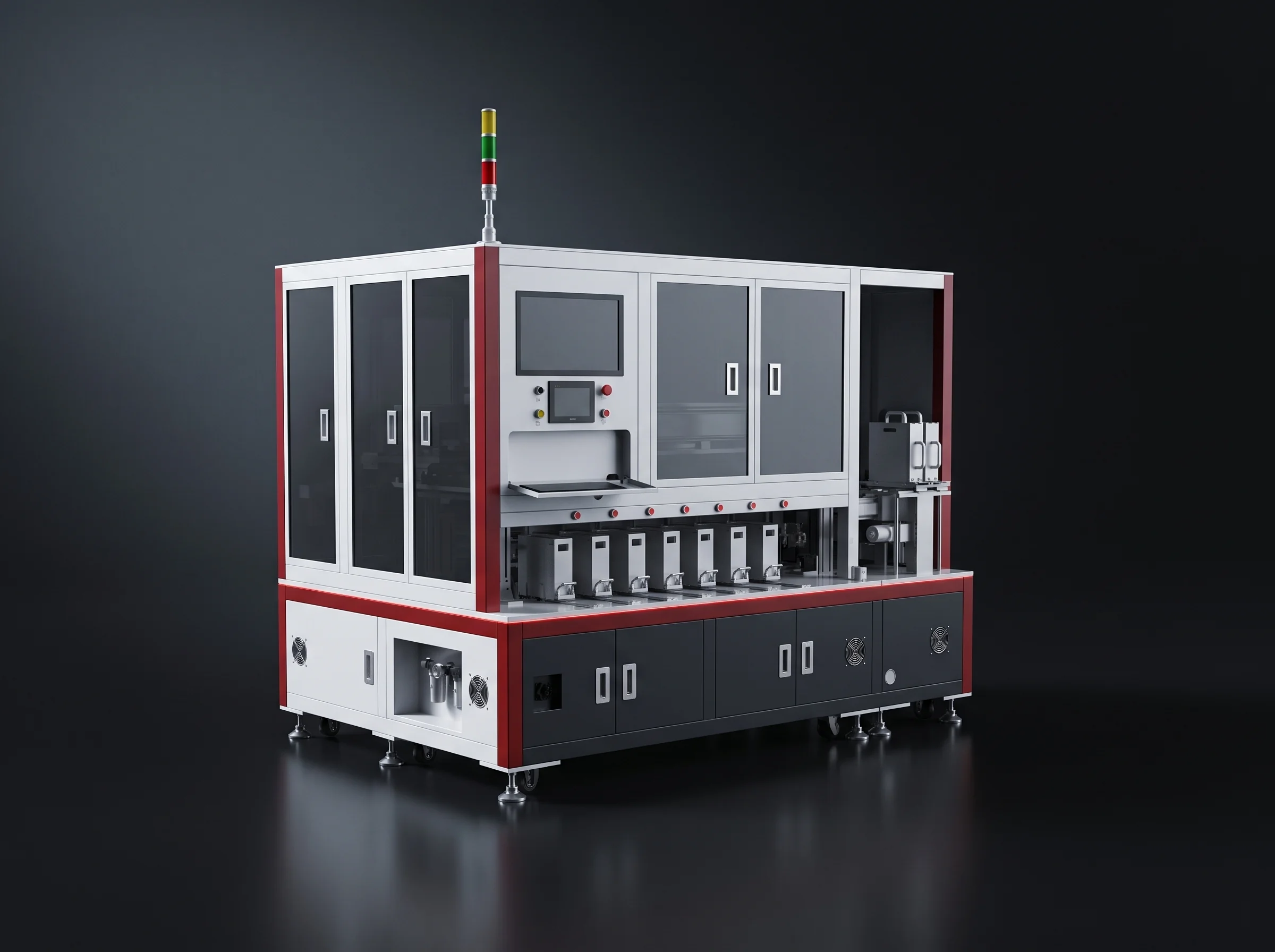
18650 automatic sorter from the cylindrical branch of the battery assembly line range
18650 automatic sorter
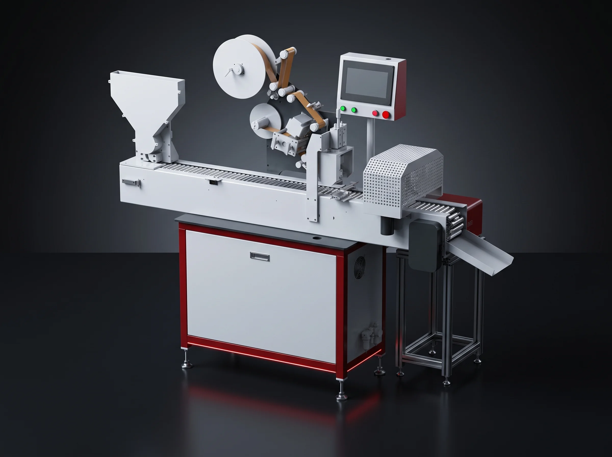
Taping machine for cylindrical and consumer cell packs
Taping machine
Plastic wrapping machine for consumer lithium packs
Plastic wrapping machine
Sealing machine on the consumer lithium pack branch line
Sealing machine
Nickel strip welding and bending machine for cylindrical packs
Nickel strip welding and bending

Also built on this branch

  • Dispensing machine for cylindrical cell holders
  • Cell back double-sided tape applicator
  • Complete cylindrical and consumer lithium pack lines

Those are described on the cylindrical and consumer pack line page.

How to reach you

[email protected]

Start a project

Start a Battery Assembly Line Project

Send the five documents and we will answer with a layout, a tier recommendation and a station list within 24 hours. For a single station, send the drawing of the part it handles and the takt it holds, and we will quote that instead of a line.

Phone / WhatsApp
Address
Wuhan, Hubei, China
Response
Reply within 24 hours

Reach the engineering team through the contact page.