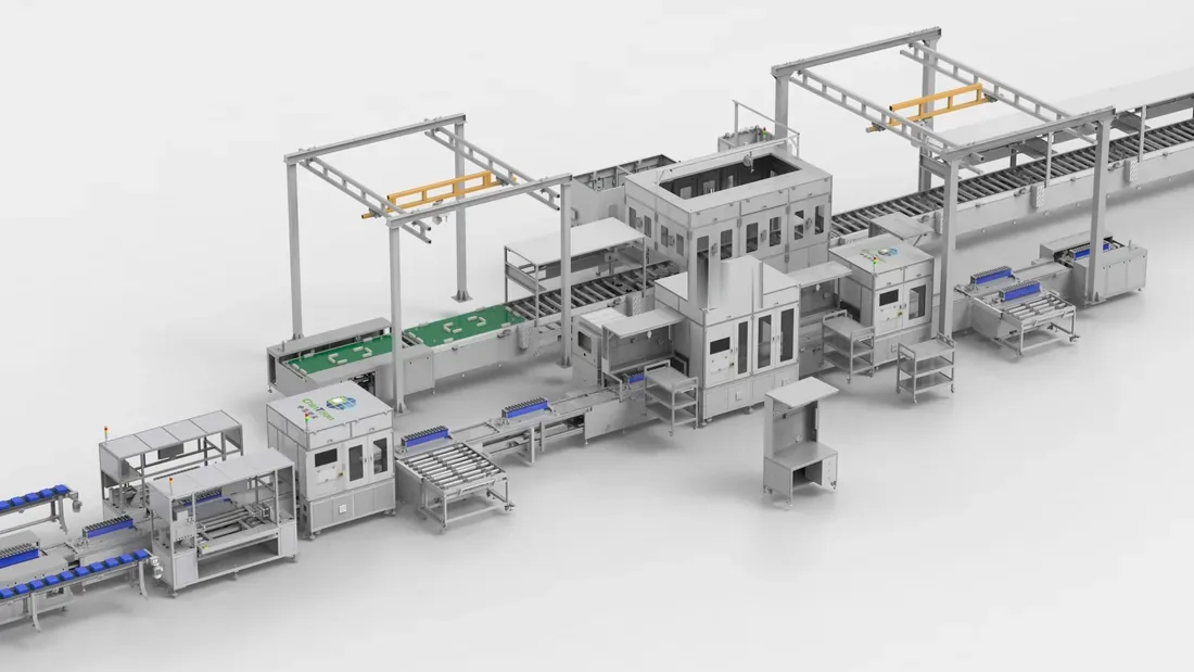
Cells in at one end, tested packs off the other — one takt across both segments +86 15327155363 [email protected]

Pack segment / 15 stations named

Battery Pack Assembly Line,
Station by Station

Prismatic module-to-pack assembly at 4–15 PPM, built around your enclosure, your liquid-cooling plate and your module — with the automation level of every station written down before you sign anything.

Where the segment stalls

  • Station 3 — enclosure floor gluing
  • Station 4 — module insertion
  • The other eleven stations — headcount
  1. 01
  2. 02
  3. 03
  4. 04
  5. 05
  6. 06
  7. 07
  8. 08
  9. 09
  10. 10
  11. 11
  12. 12
  13. 13
  14. 14
  15. 15

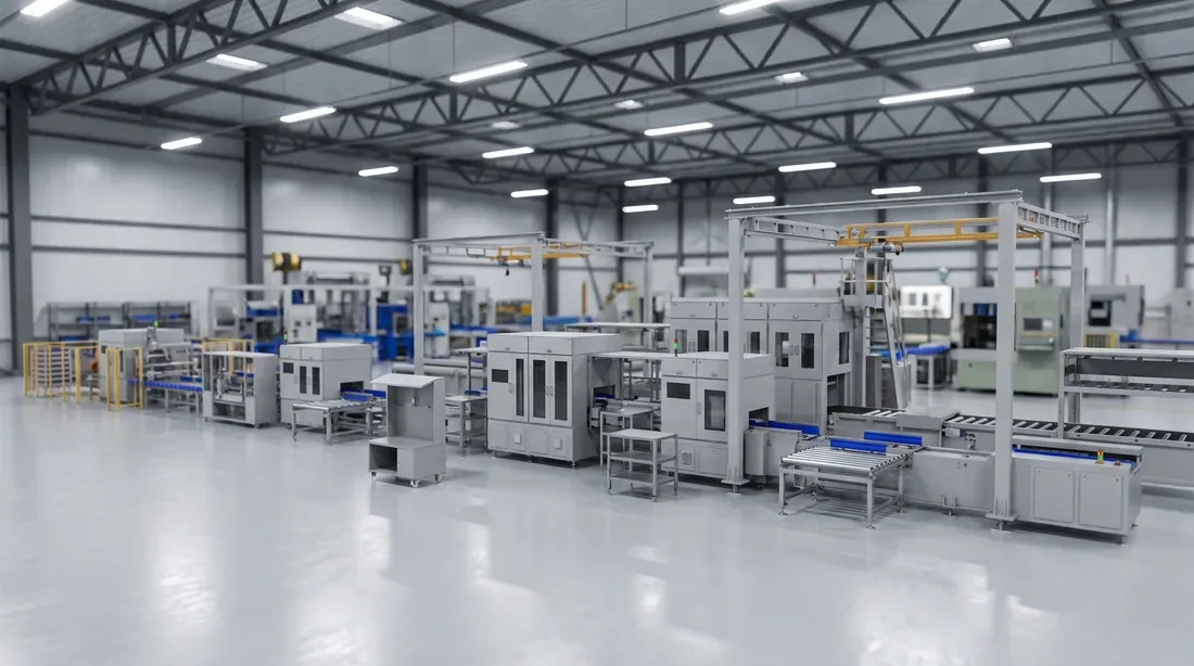
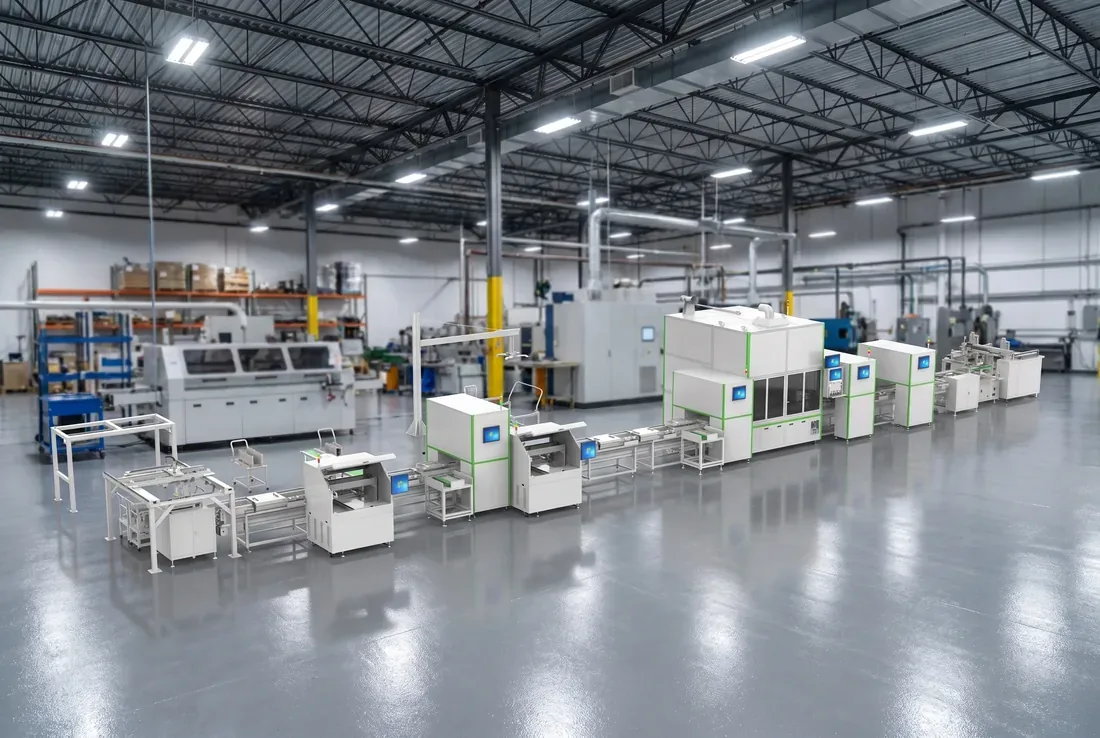
The pack segment, station 01 to station 15 — station 03 is the only automated one

You have the cells and you have the order. What you don't have yet is the back end.

Most of the projects that reach us are at roughly the same point.
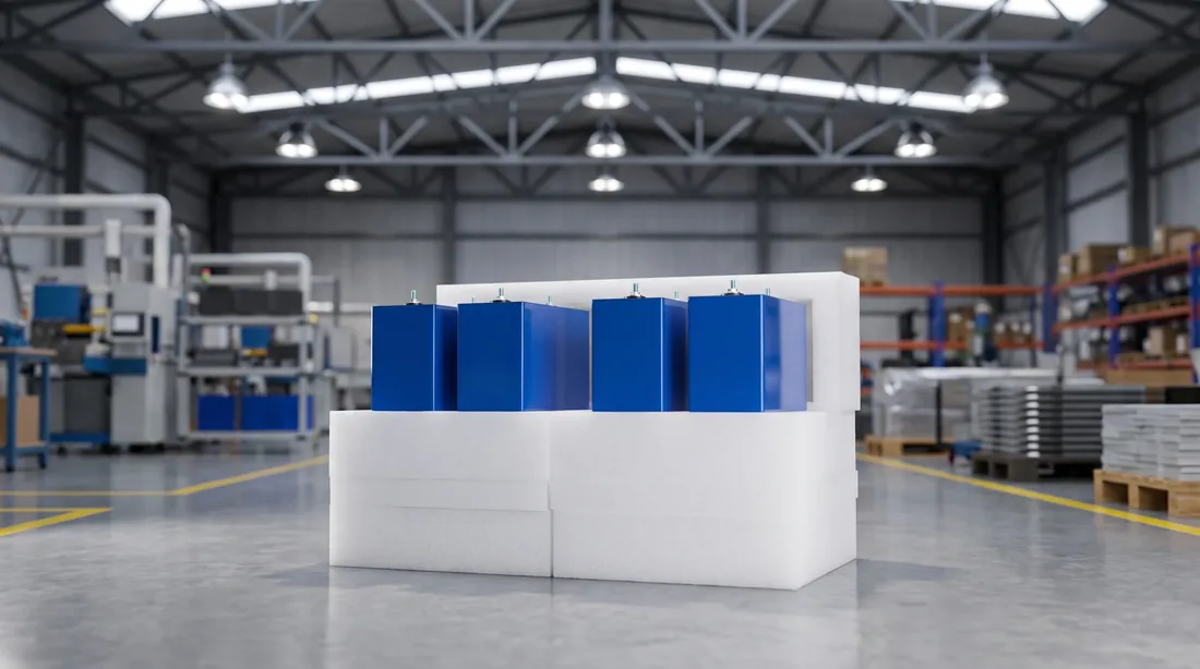
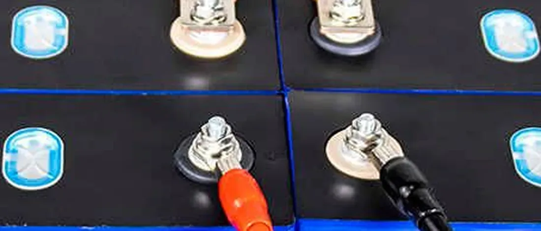
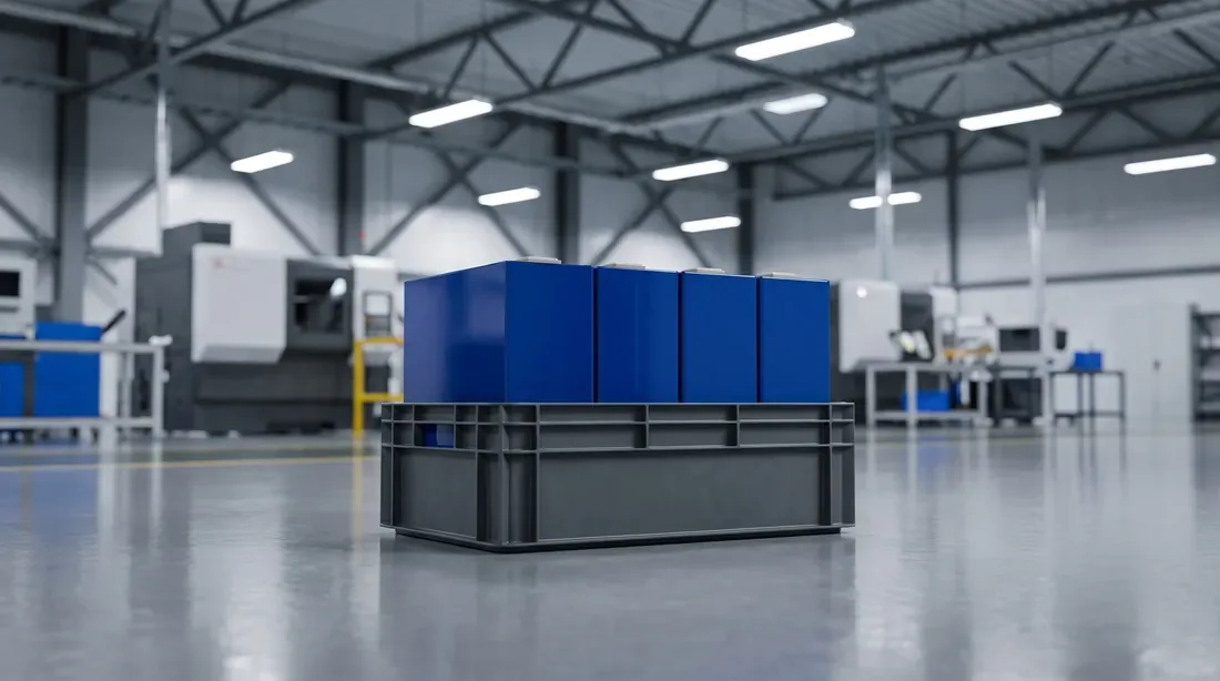
Prismatic energy-storage cell of the format this pack line is built around
The cell — already contracted
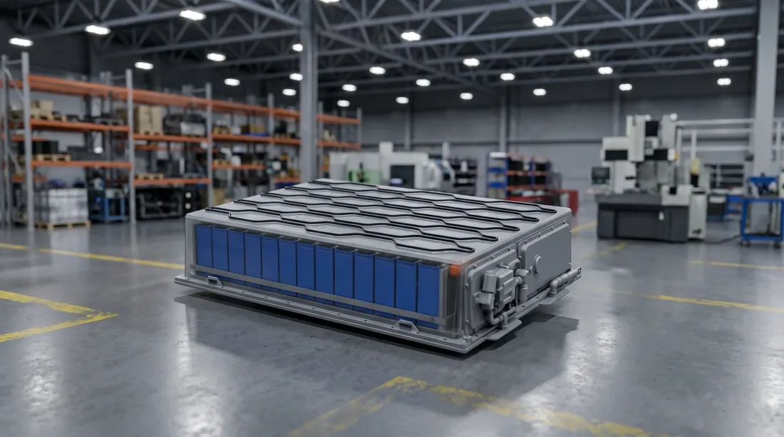
Pack enclosure and liquid-cooling plate before modules are installed
The enclosure and the plate
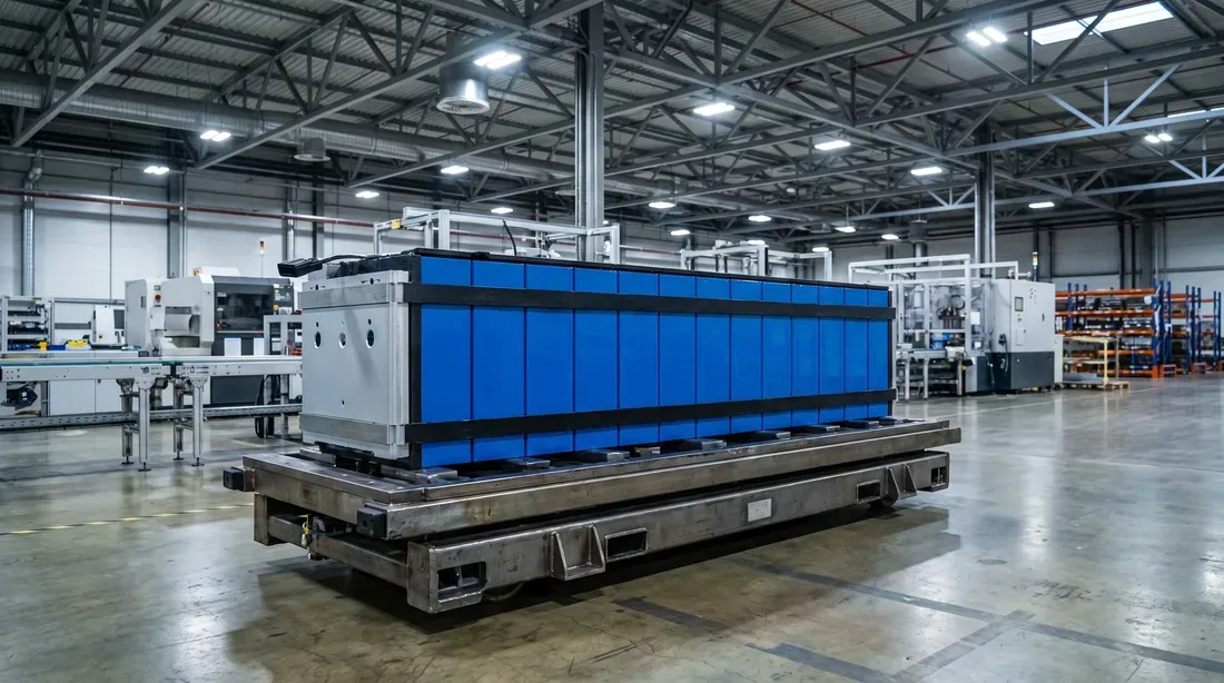
Assembled module arriving from the module segment
The module — arriving on a carrier

The cell is decided

280 Ah or 314 Ah prismatic, already contracted, already the thing your pack drawing is built around.

So are the enclosure and the cooling plate

Usually by a fabricator who has never seen the assembly line the boxes are going to travel through.

The output figure is already promised

The takt that follows from it is not a preference, it is an arithmetic result.

The bay is fixed

Length, width and clear height were set when the building went up, and the line is the thing that has to bend.

Scope, so nobody wastes a call

We take over once the cells are inside your gate — sorting, module assembly, pack assembly, testing, offload. Cell production upstream of that is not ours.

Three places a pack segment stalls, and the station where each one happens

None of these appear on a line drawing. All three appear in week two of ramp-up.
Module part-way into a pack enclosure at the insertion station
A module halfway into a box

Station 4 — module insertion

The enclosure, the cooling plate and the module were dimensioned by three parties who never met. On paper the module fits. On the floor it fits after somebody files a bracket. The line does not slow down at Station 4, it stops there, and the four stations upstream fill with work-in-process while a fitter improvises. The workaround is always the same shape: shim it, tap it in, catch up on the next shift.

Station 3 — enclosure floor gluing

The bead is thermal path, and it is the station no competing quote will discuss with you. Short bead and the pack runs hot at the module the cooling plate was supposed to reach. Heavy bead and adhesive squeezes past the module foot into hardware that has to come back out. Neither failure announces itself at the station that caused it.

The other eleven stations — headcount

Series busbars, BMS, MSD and connectors, harness dressing, cover, tightening, front panel: these are hand-work, and every supplier's brochure calls the line automated anyway. So the TCO model gets built with an automated segment's manning, and the real number is discovered at commissioning, when the operators do not exist and the takt does.

A pack line rarely stops where the drawing says it will. It stops at Station 4, with a module halfway into a box.

The enclosure

Correct on its own drawing.

The module

Also correct on its own drawing.

The clearance between them

Nobody's job by default — which is why it is Station 4.

The pack segment: fifteen stations, named

Automation levels below describe the BLP-P8 standard configuration. Modules arrive from the module segment; packs leave tested and offloaded.

  1. Station 01Enclosure and liquid-cooling plate loading and cleaning MANUAL
  2. Station 02Liquid-cooling plate leak test MANUAL
  3. Station 03Enclosure floor gluing AUTO
  4. Station 04Module insertion MANUAL
  5. Station 05Module fixing MANUAL
  6. Station 06Series busbar installation MANUAL
  7. Station 07BMS installation MANUAL
  8. Station 08MSD and HV/LV connector installation MANUAL
  9. Station 09Harness dressing MANUAL
  10. Station 10Top cover installation MANUAL
  11. Station 11Top cover tightening MANUAL
  12. Station 12Front panel installation MANUAL
  13. Station 13Whole-pack air-tightness test MANUAL
  14. Station 14Pack EOL test MANUAL
  15. Station 15Pack offload MANUAL
MANUAL describes who handles the work, not what does the measuring. Stations 2, 13 and 14 are test instruments that run their own cycle and give their own verdict — an operator loads the part, starts the cycle and reads the result.
Movement and positioning between stations is the conveyor's job, not the operator's — see the conveyor system page. Test thresholds for Stations 13 and 14 are stated once, on the pack EOL testing page.
Station 1 — enclosure and liquid-cooling plate loading
Station 01 — loading
Station 6 — series busbar installation
Station 06 — busbars
Station 13 — whole-pack air-tightness test
Station 13 — air-tightness
Station 15 — pack offload
Station 15 — offload

A bad bead at Station 3 is found at Station 13, ten stations later

That gap is the reason this is the one station in the pack segment that runs automated.
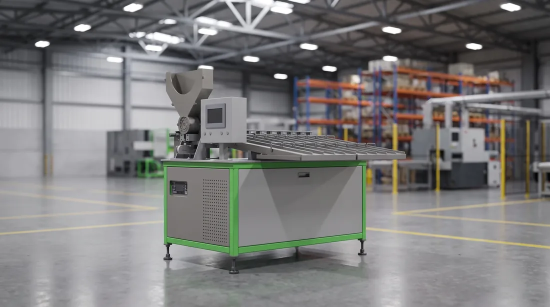
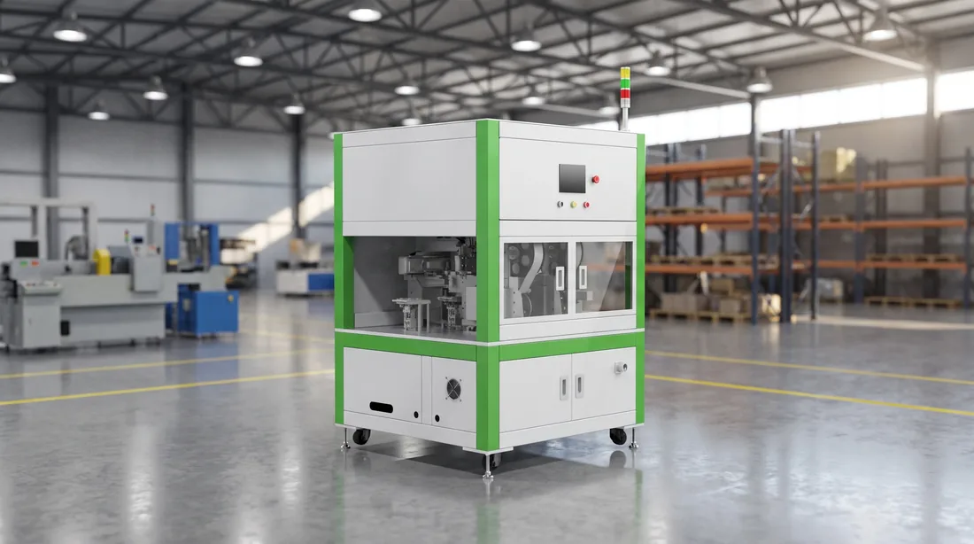
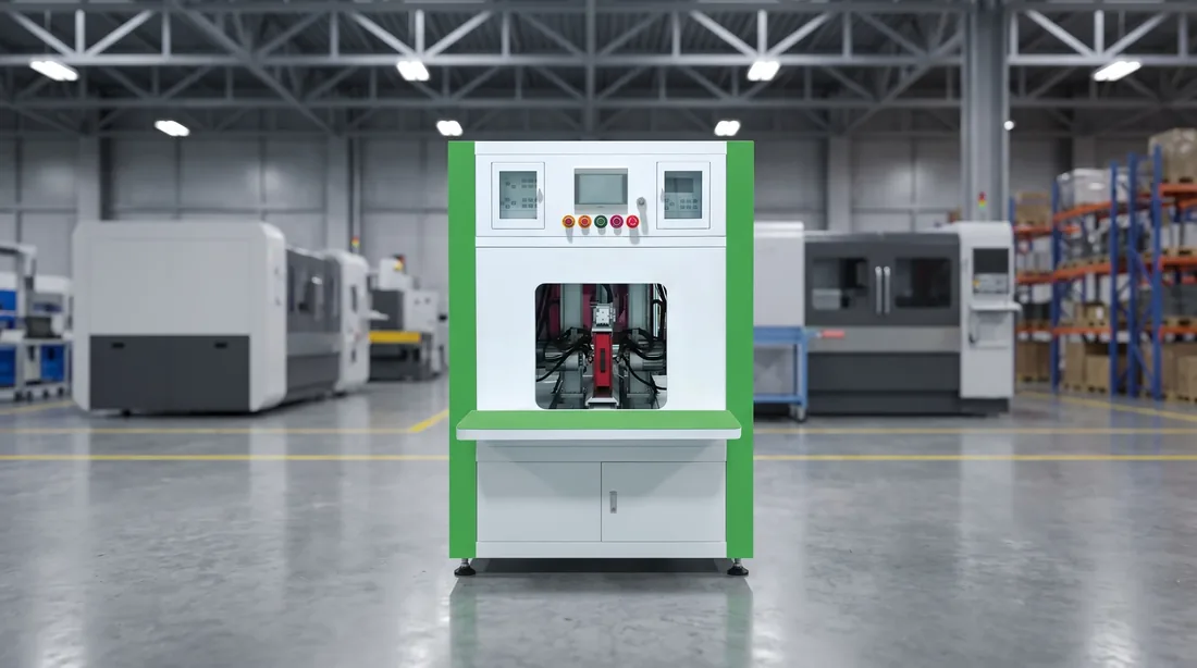
Vision-guided adhesive dispensing station over a pack enclosure floor
Station 03 — the dispensing head
Closed pack at the air-tightness test, ten stations after the bead was laid
Station 13 — where a bad bead finally reports

Count what is already inside the box

By the time whole-pack air-tightness gives its verdict: modules inserted and fixed, series busbars, BMS, MSD and connectors, harness dressed, cover on and tightened, front panel made up. Ten stations of hand-work sit on top of a bead nobody can see any more.

A pack that fails there does not fail cheaply

It goes backwards through the same ten stations, and the parts that come off it — sealing faces, harness ties, fasteners — are not all parts you put back on.

The same gap distorts your yield picture while you are ramping

Station 13 reports a sealing problem; the problem was made at Station 3, on a shift that has already gone home; and the operator at Station 3 gets no signal either way.

So the bead does not get judged by eye here

Station 3 runs two closed loops — vision, so the bead lands on the enclosure that is actually on the fixture, and metering, so the volume laid down is the volume commanded.

Positioning, path and dispense-volume figures for this station are stated once, on the liquid-cooling plate gluing station page.

Adhesive bead laid on the enclosure floor
The bead path, close

Station 4 is a tooling problem, and it gets solved before the line ships

Insertion clearance is designed against your enclosure, your plate and your module — not against a blueprint pack.

Tooling is cut to your three drawings

We ask for the enclosure drawing, the cooling plate drawing and the module drawing before the line is cut, and the insertion and fixing tooling at Stations 4 and 5 is built to those three — so the clearance question is settled on paper while it is still cheap to settle.

The module arrives located, not shoved

Modules arrive at Station 4 located by the conveyor rather than pushed into rough position by hand, which is what makes a hand-loaded insertion station repeatable.

The line bends to the building

Layout is adjusted to the bay you already have — the building does not get rebuilt for the line.

Blueprint cell, module and pack dimensions for ESS packs are stated once, on the energy storage pack line page. Compatibility envelopes, and what a change of cell or module costs you in tooling and downtime, are on the compatibility and changeover page.
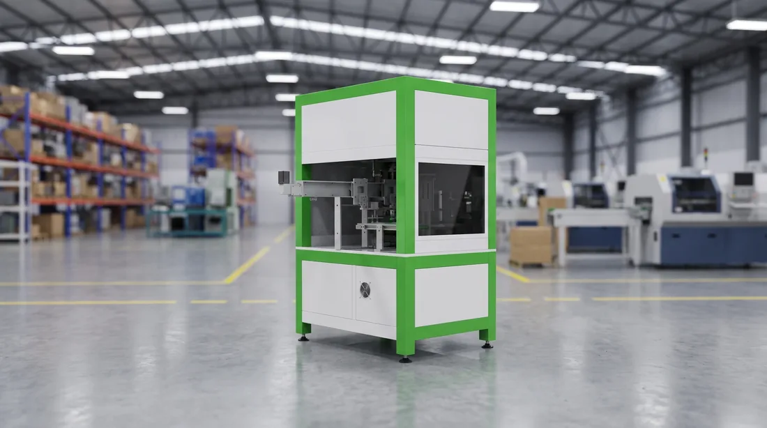
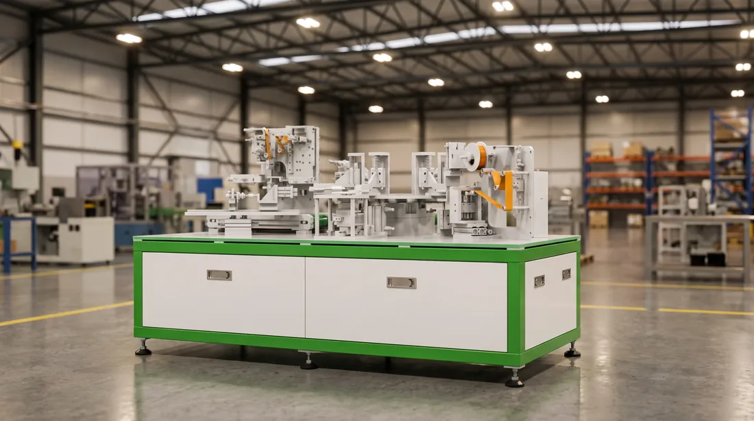
Module insertion station of the pack segment
Station 04 — insertion
Insertion and receiving tooling cut to the customer's enclosure and module
The tooling itself
Module located by the conveyor before insertion
Located before it is lifted

Three drawings decide the tooling, and each one decides a different set of stations

Send them once, before the line is cut, and the tooling question stops being a conversation about goodwill.

Your enclosure drawing

Station 1 (how the box is presented and held), Station 3 (where the bead runs on the floor), Station 4 (the clearance a module has to drop through), Stations 10, 11 and 12 (cover, tightening, front panel) and Station 13 (the sealing fixture the air-tightness test closes onto). Seven of the fifteen rows above are dimensioned from that one drawing.

Your liquid-cooling plate drawing

Station 1 (how the plate is loaded and cleaned), Station 2 (the fittings the leak test connects to) and Station 3 (where the bead has to land relative to the plate). Three stations, and two of them are tests — which is why a plate drawing that arrives late arrives too late.

Your module drawing

Station 4 (insertion tooling), Station 5 (the fixing pattern) and Station 6 (the reach the series busbars have to cross). It is the drawing that has to agree with the module segment as well, because the module leaves that segment on a carrier dimensioned from the same figures.

What a missing drawing costs

Tooling that has no drawing gets built to a blueprint pack instead. The difference between your part and the blueprint does not appear on paper — it appears at the station, on your floor, with a fitter and a file.

What to ask any supplier

Which stations does each of my three drawings decide? It is answerable in one page if the line is being designed around your parts, and unanswerable if a standard line is being quoted at you.
The end of the pack segment where the enclosure drawing decides the tooling
Stations 10 to 13 — all dimensioned from one drawing

Fourteen stations are hand-work. The conveyor is what makes hand-work repeatable.

MANUAL says who does the work. It does not say the part arrives wherever it happens to land.

  1. Step 01

    Arrive

    The module reaches the station on its carrier, paced by the line rather than by the operator.
  2. Step 02

    Stop

    A stop holds the carrier at the station instead of letting it drift past.
  3. Step 03

    Lift and locate

    A lift raises the module and seats it against the fixture, so position is set by tooling.
  4. Step 04

    Release

    The carrier is released when the station is clear, and the next one comes forward.

What that takes away from the operator

Position. Hand-built does not have to mean hand-positioned, and that is the whole difference between the first pack of a shift and the last one — the fixture sets where the work lands, not the person.

What it means for takt

The part comes to the operator; the operator does not walk the line chasing it. Every hand station gets the same window, which is what lets a published takt figure mean anything on a segment that is mostly people rather than machines.

Why the line is panelled on both sides

People work beside this segment all shift. The conveyor runs with side panels along its length, which keeps dust off the work and hands out of the moving section — a hand-built segment has to be safe to stand next to, not just possible to staff.

Carrier load, conveying speed and the stop-and-lift positioning modules themselves are stated once, on the conveyor system page.
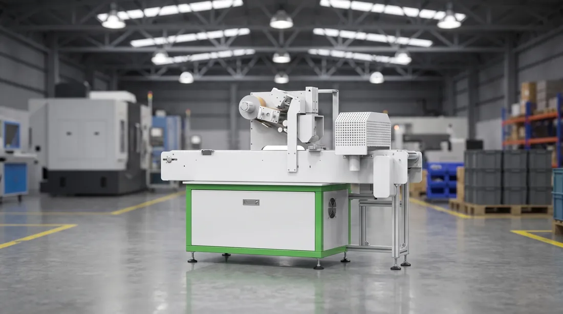
Stop-and-lift position where the conveyor hands a module to the operator
Where the line hands over

What the pack segment actually costs you in people

Twelve to fourteen is the number that belongs in your TCO model, and it is the one most quotations leave out.

12–14 Operators staffing the pack segment
BLP-P8S and BLP-P15
A single hand-work station in the pack segment
One bench — the unit of headcount
15Stations in the pack segment
1Automated station in a BLP-P8 pack segment
≥99%Line acceptance yield, equipment-caused only

It is a hand-built segment with one machine in it, and it is cheaper to staff it on purpose than to discover it at commissioning. A brochure that calls this segment automated is not describing the line you would be buying.
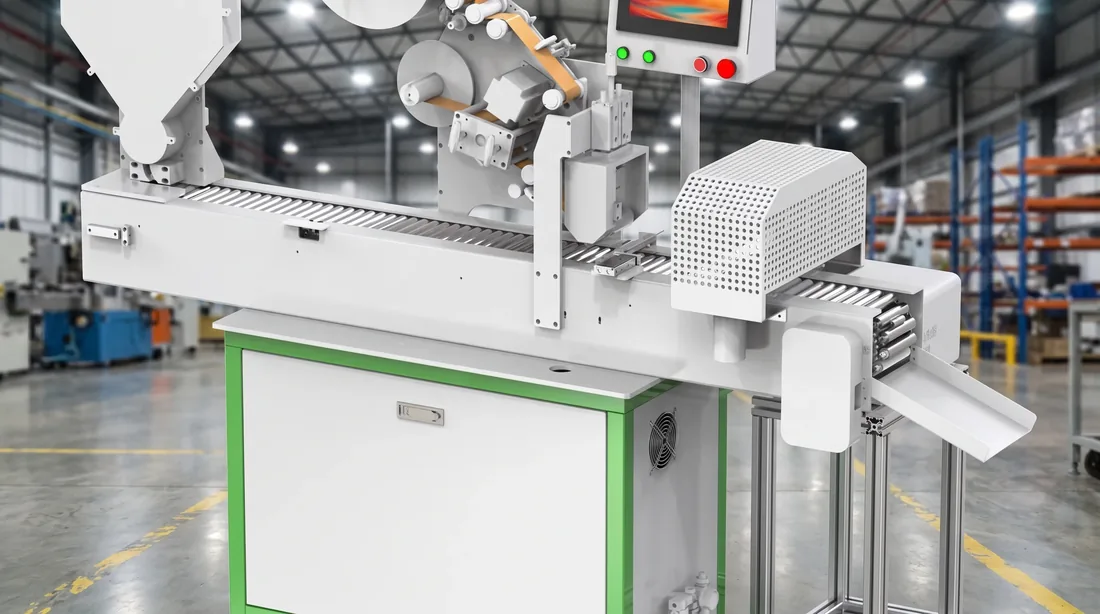
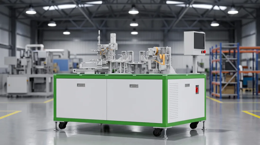
Hand-work stations along the pack segment of a battery pack assembly line
The segment, bench after bench

Send three things, get a layout back

Cell spec, target PPM and bay dimensions with clear height. That is enough to come back with a layout and a station list.

Reply within 24 hours / Everything else we need is listed on the contact page

You can sign this line off one station at a time

What is written above is what goes into the acceptance document — the same fifteen rows, the same levels.

Auto Manual
01

Every station carries its level

So headcount and running cost are computable while you are still comparing quotes, not after the line is bolted down.
02

≥99% goes in the document

Line acceptance yield, counting equipment-caused defects only, is a figure we are willing to have written into the acceptance document rather than one that lives in a brochure.
03

Tooling is checkable on a drawing

Insertion and fixing tooling is dimensioned to your enclosure and your module, and the layout to your bay — both are things you can check before anything ships.
04

The sequence is published too

The acceptance sequence itself, and what each side has to bring to FAT and SAT, is set out on the acceptance page.
Pack end-of-line test station
Station 14 — where the verdict is produced
Finished assembly at offload, ready for acceptance
Station 15 — where it is handed over

Name the position you think is your bottleneck

A segment retrofit is a complete enquiry on its own, quoted the same way a whole line is.

If one of the fifteen is already the constraint
Say which one. That is a shorter conversation than a whole-line quotation, and it starts from the same station list.
Phone / WhatsApp
Address
Wuhan, Hubei, China
Response
Reply within 24 hours
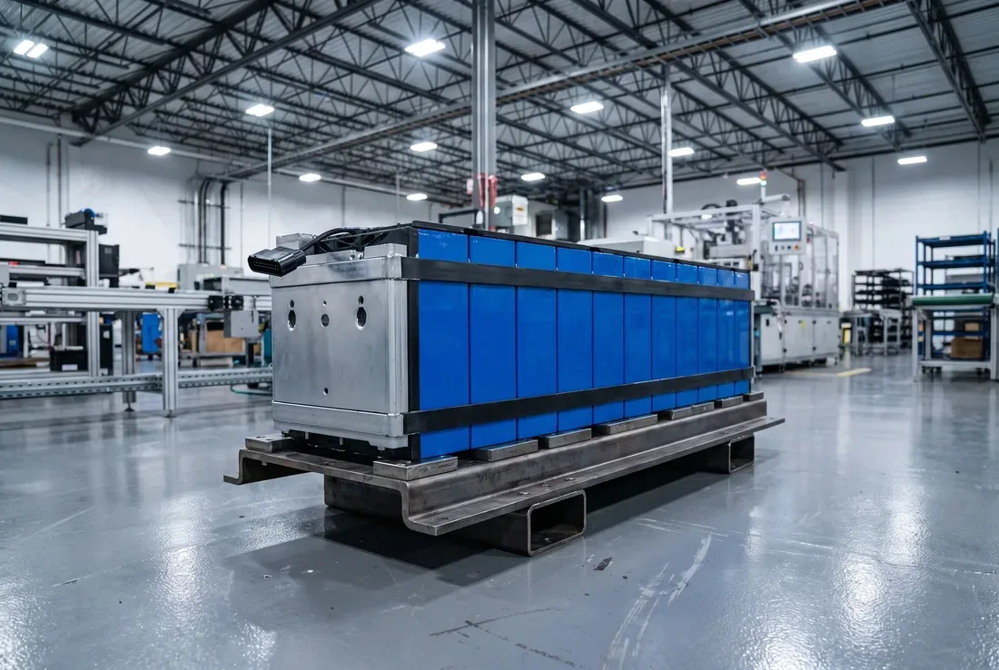
Finished energy-storage pack coming off the line
What comes off the end of the pack segment