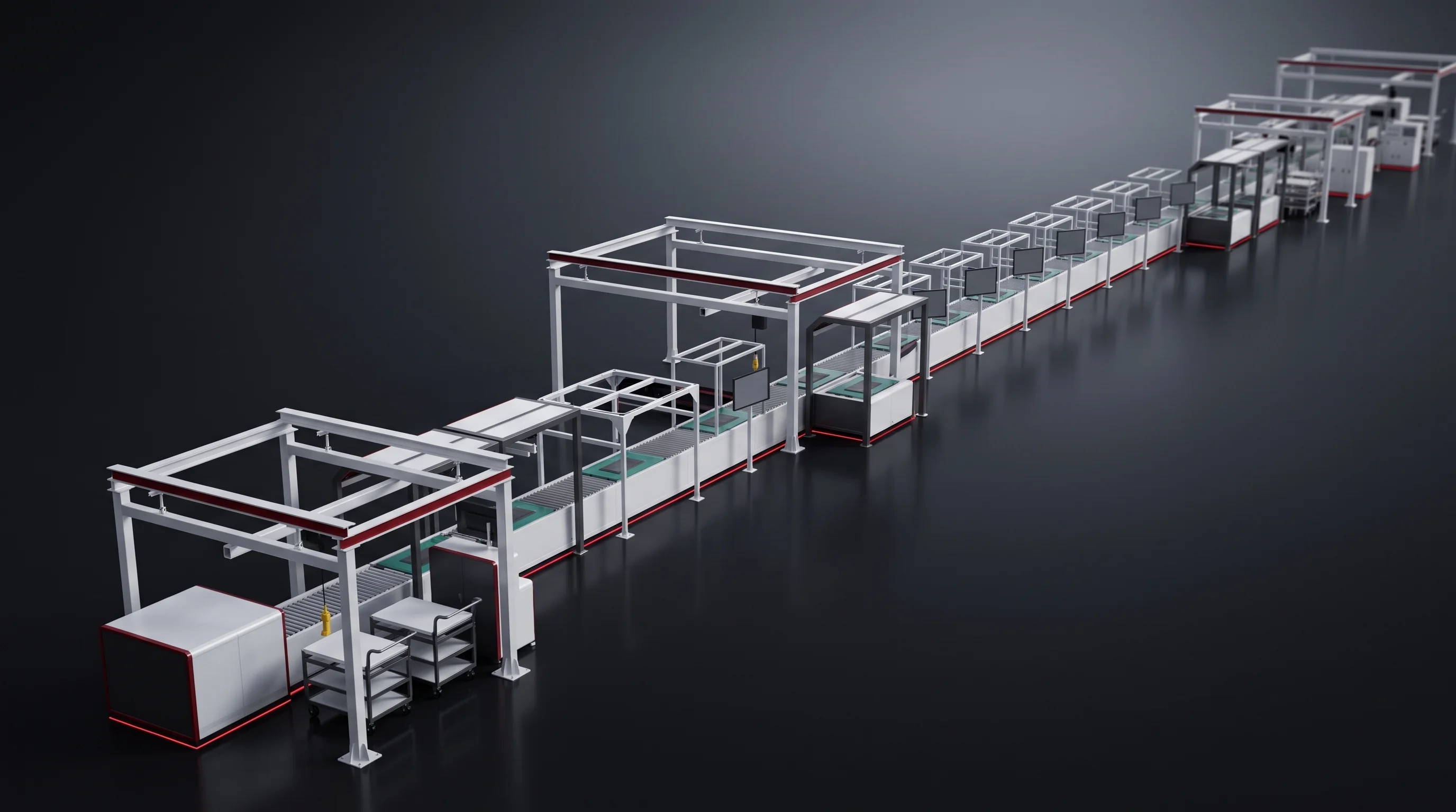
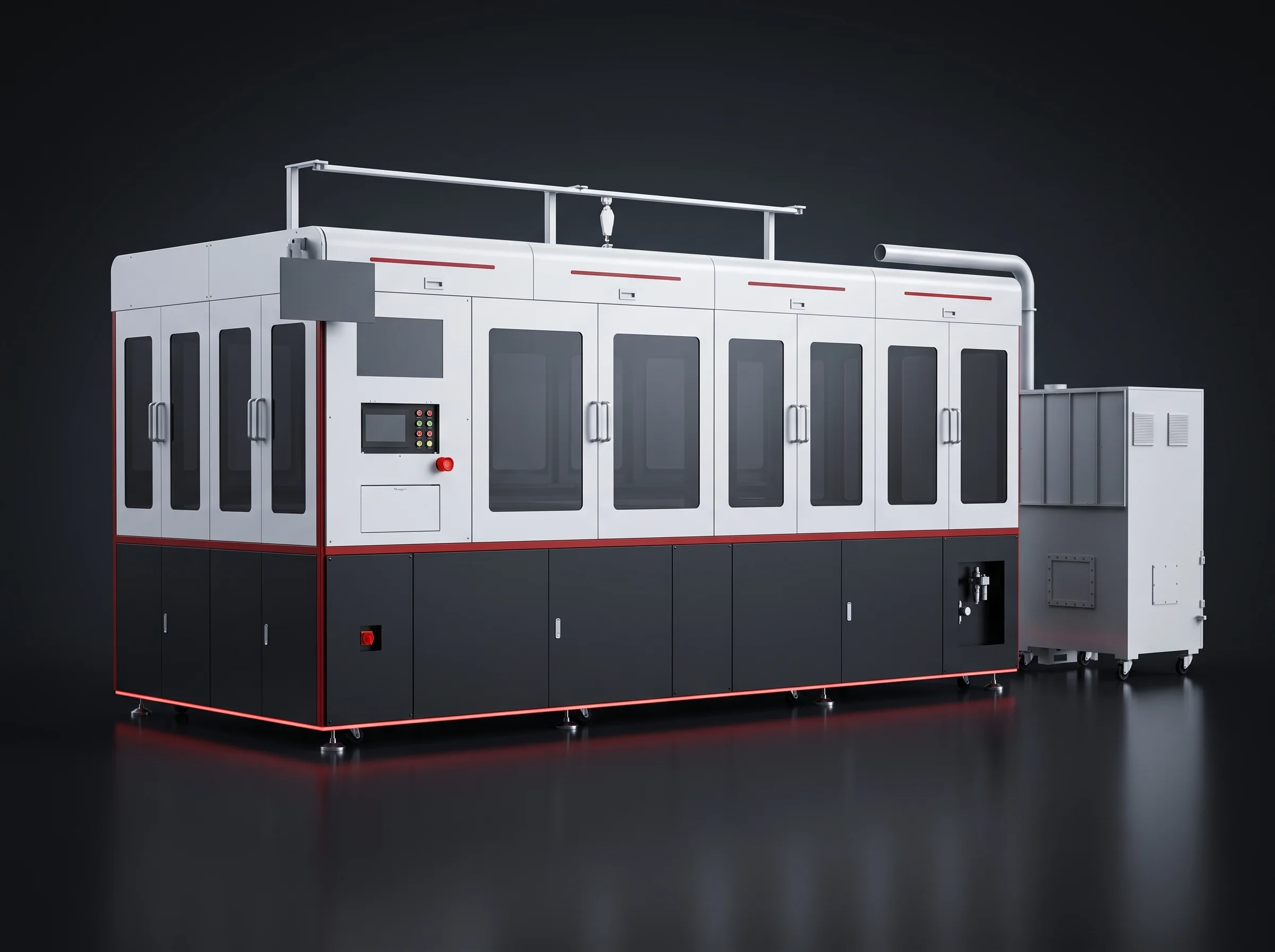
BLP-WG — off-line, four-axis
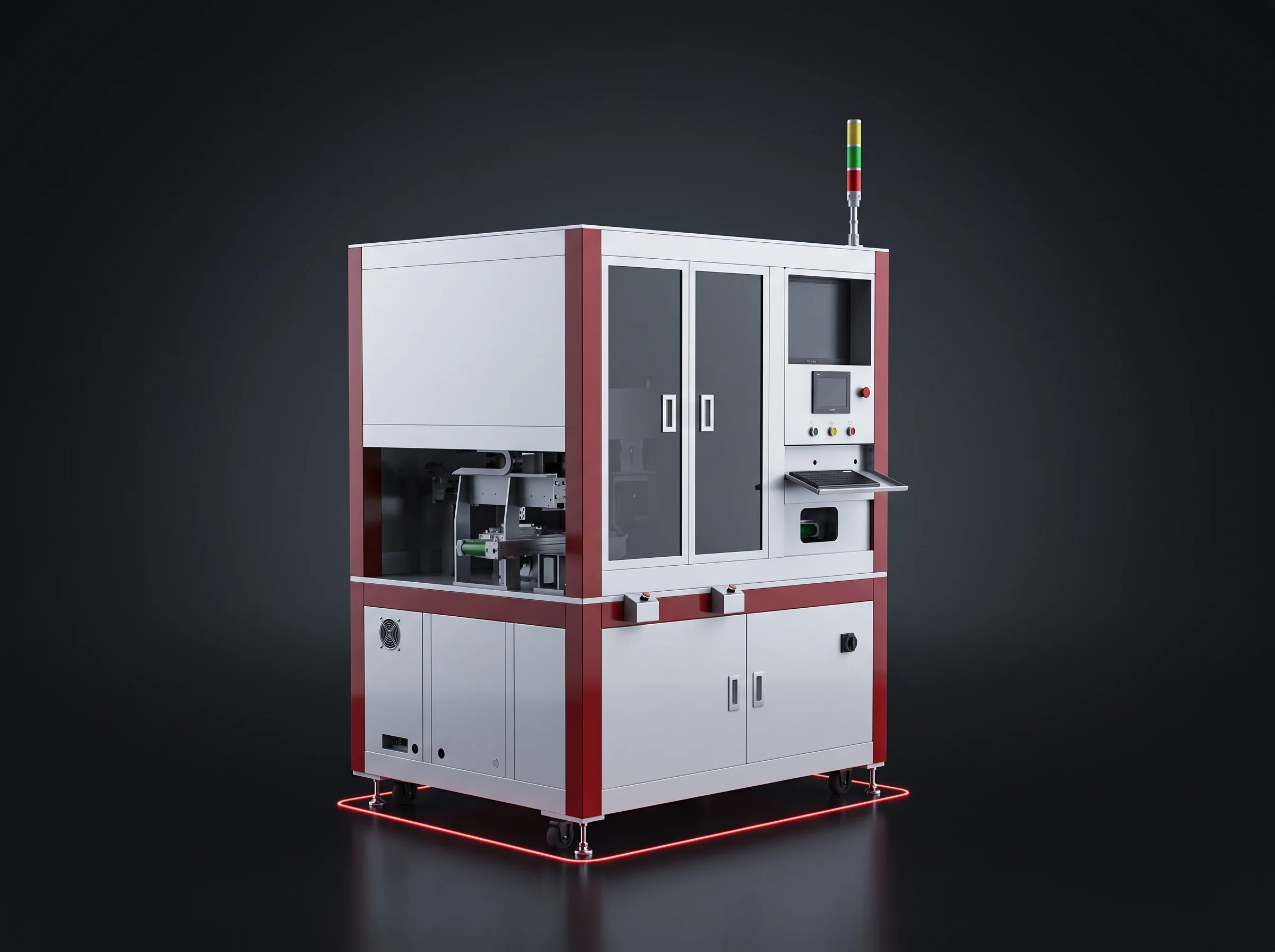
The BLP-WG Off-Line Gantry Laser Welding Machine
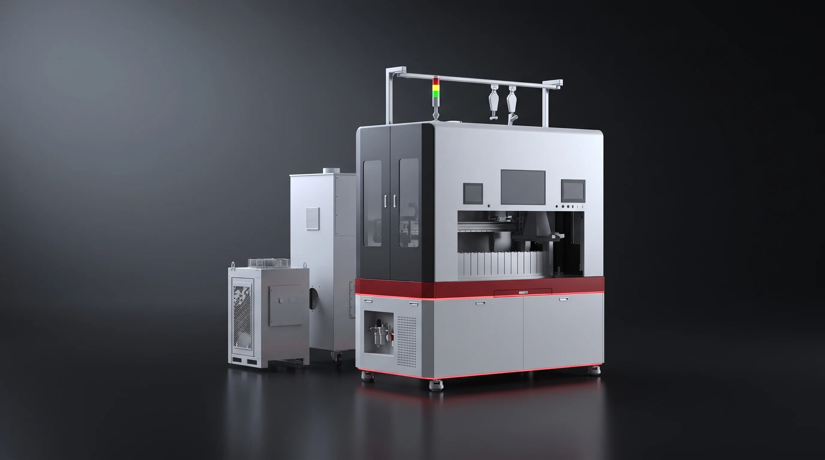
A welder that stands on its own floor rather than inside a line. Work is clamped to its table by hand, welded to a stored recipe, carried away again — first articles, rework and short runs, while the line runs on.
- 1070 nmFibre source, 1000–6000 W
- ±0.01 mmRepeat positioning
- 4–6 PPMOn the reference part
- 4 × 2 mFootprint, ancillaries counted in
The machine
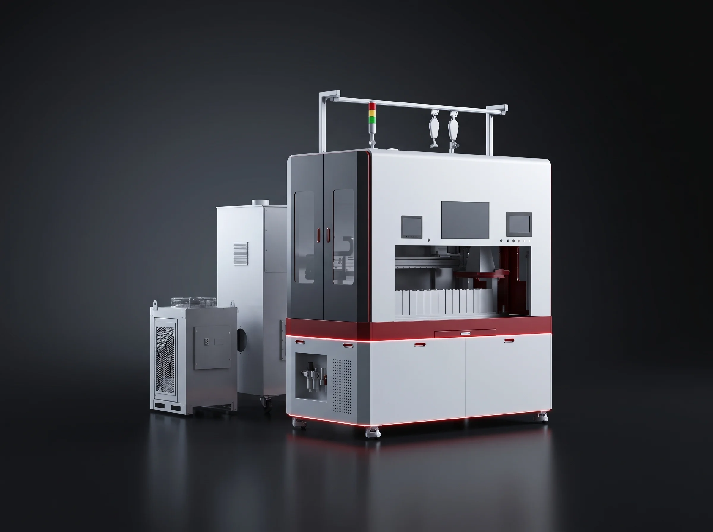
The BLP-WG Gantry Laser Welding Machine
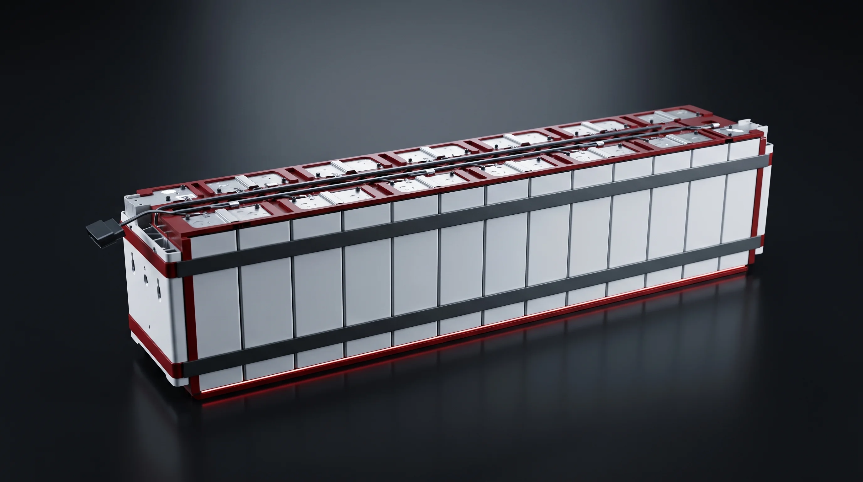
Busbars, connectors, brackets and strip parts, on a fixed table under a four-axis gantry.
A 1070 nm fibre source in four power options, repeating to its own datum within ±0.01 mm, on 4 × 2 m of floor with the laser ancillaries counted in.
Two buyers, one machine
The process and equipment people inside module and pack plants: the ones already running a line who need somewhere to put the work it cannot absorb, and the ones building packs in low volume who need a welder that answers to a fixture rather than to a takt.
Because this gantry laser welding machine asks the line for nothing, it drops in behind one of our module assembly lines or behind a line built by anyone else, with its own supply, its own footprint and its own chiller.
Sold on these figures
- Wavelength
- 1070 ± 10 nm
- Source power
- 1000–6000 W
- Repeat positioning
- ±0.01 mm
- Rate
- 4–6 PPM
- Footprint
- 4 × 2 m
- Behind a running line, or on its own
- Inside the takt is a different machine — the in-line busbar welding station
Axis by axis
Four Axes Under One Program
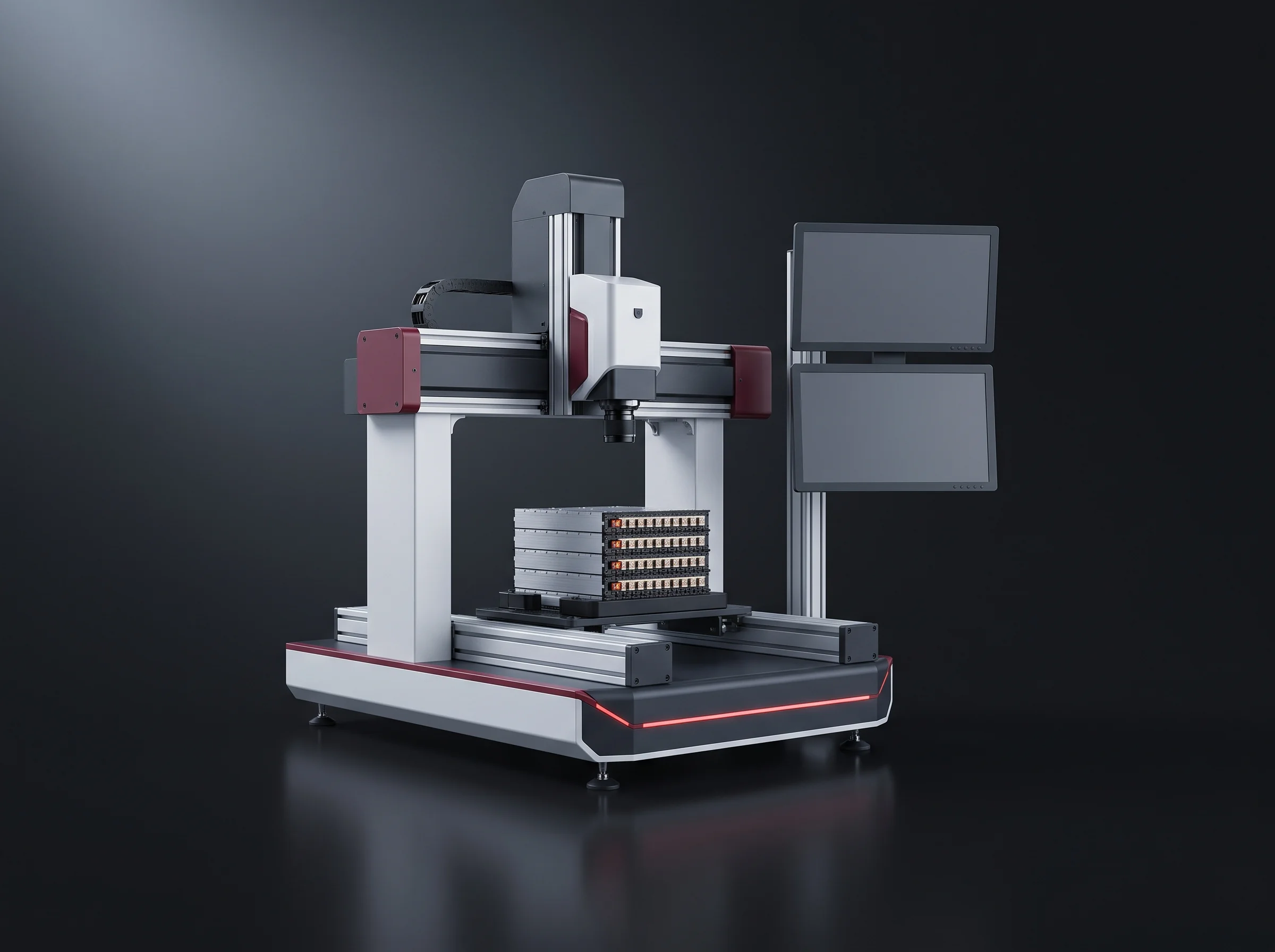
Three linear travels and the head, under one program. The part does not move under its own power — which is why every figure here is written against a part somebody clamped.
The gantry and its three travels
X runs the long dimension of the table, Y across it, Z above it. The head rides the gantry; the work stays put.
- X
- 800 / 1000 mm
- Y
- 400 / 600 mm
- Z
- 200 / 400 mm
The table and your fixture
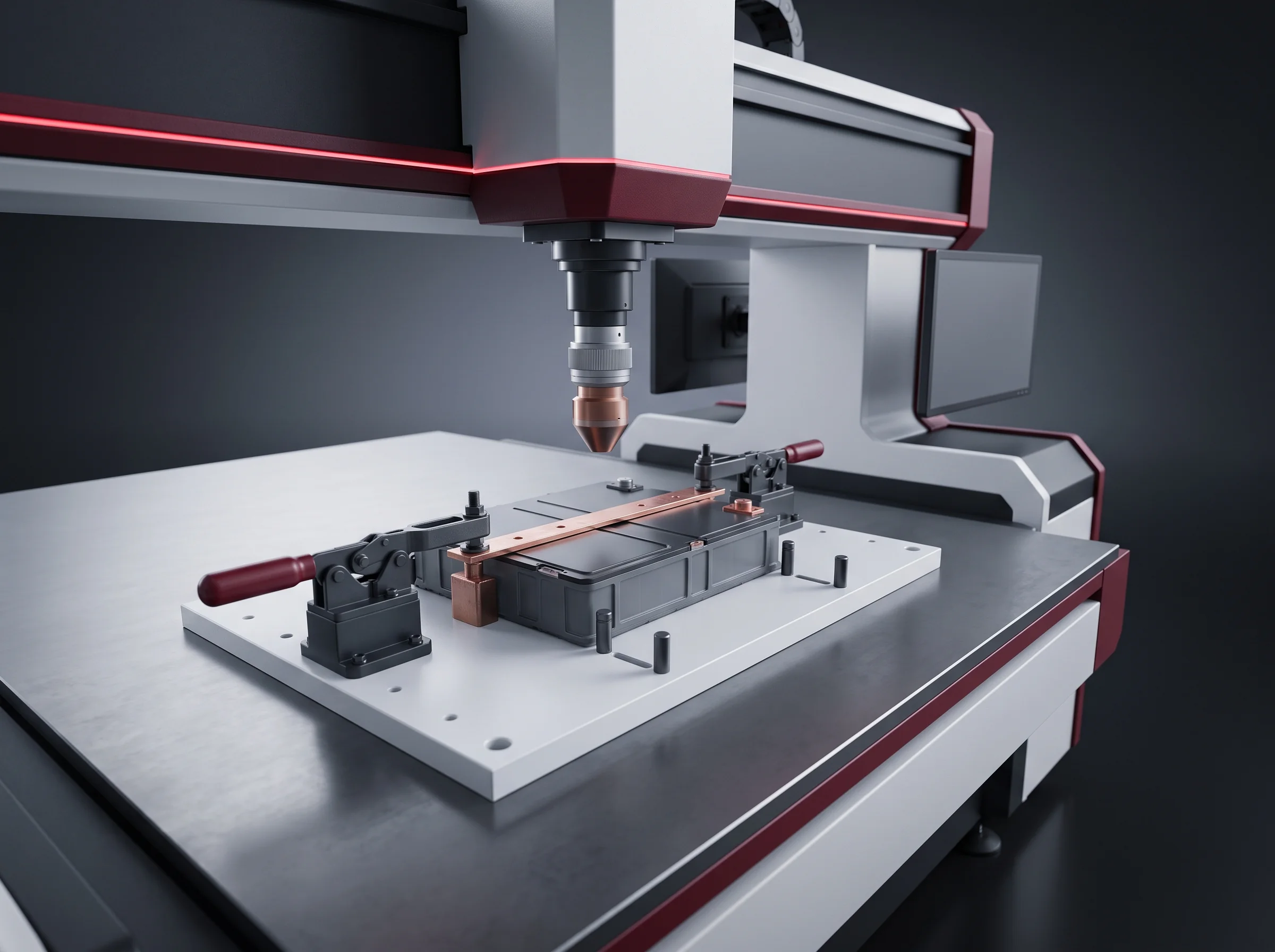
A fixture cut for one part gives the machine its datum, and decides how much of the published travel you actually get to use.
- Datum
- Your fixture
- Loading
- By hand
- Clampings
- Per part
The source, outside the frame
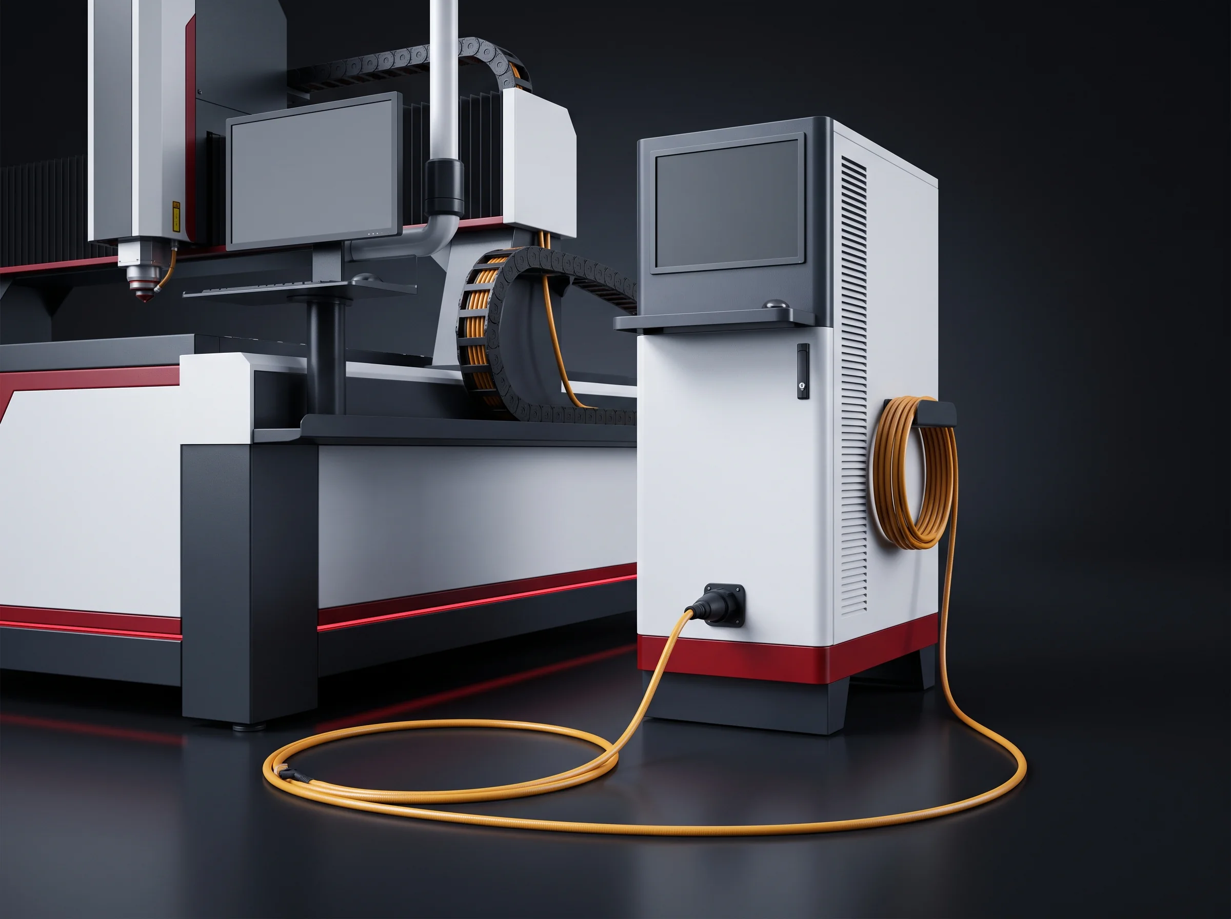
It sits outside the frame and delivers through the fibre. Power is one of four options, the core one of four diameters, ordered as a pair.
- Adjustment
- 10–100%
- Stability
- Within 3%
- Core
- 14–100 µm
CCD positioning, ordered by the line
Finds a feature on the part itself, not a position on the machine. Written into the quotation, never assumed.
- Accuracy
- ±0.01 mm
- Status
- Optional
- Quoted
- Own line
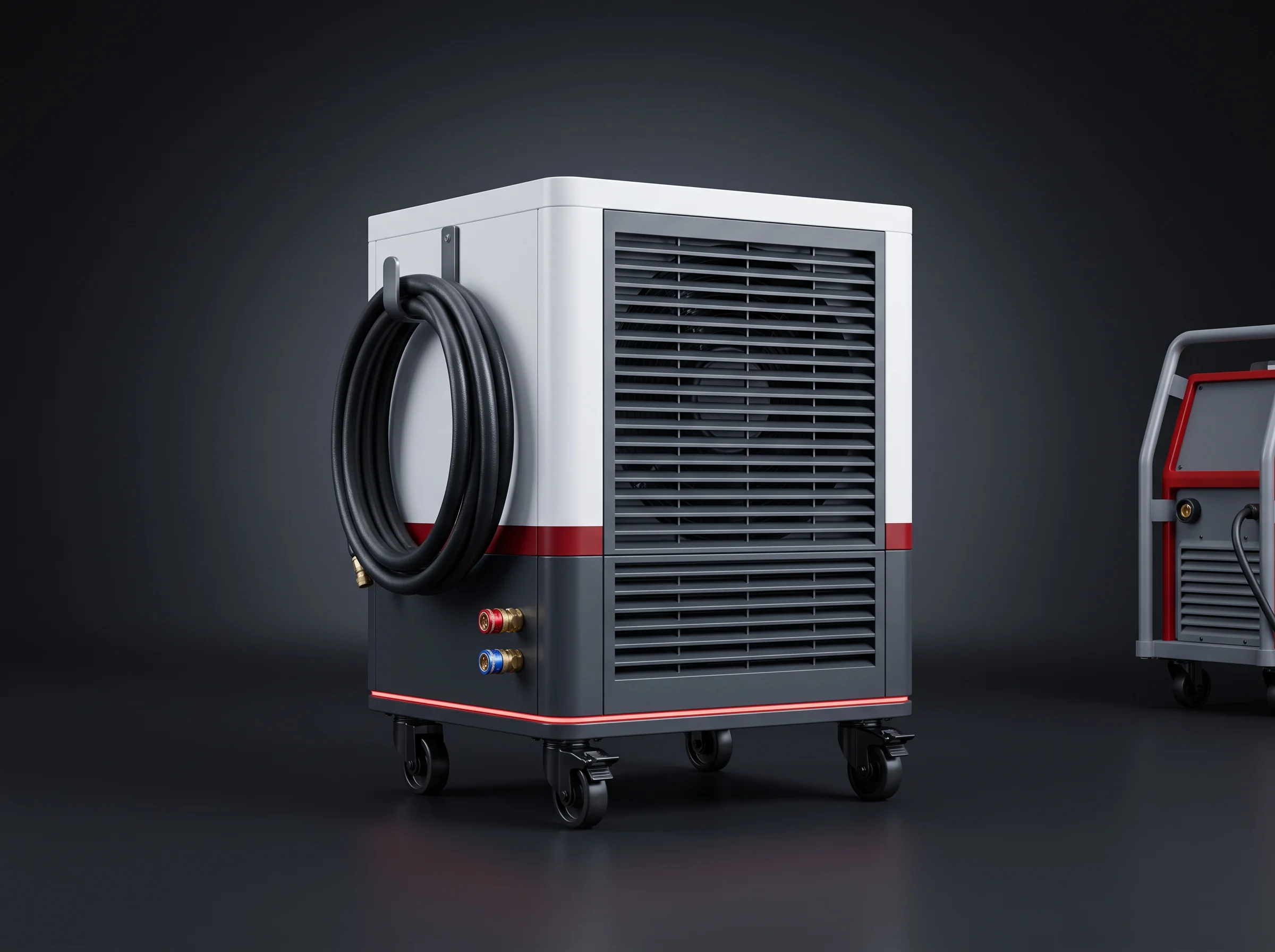
Cooling is a second object
The chiller is not an accessory hidden in the frame. It needs its own floor and service access, and belongs on the layout drawing at the same time as the machine.
What it does all day
Three Jobs On The Table
Work a line cannot take, or should not be stopped for.
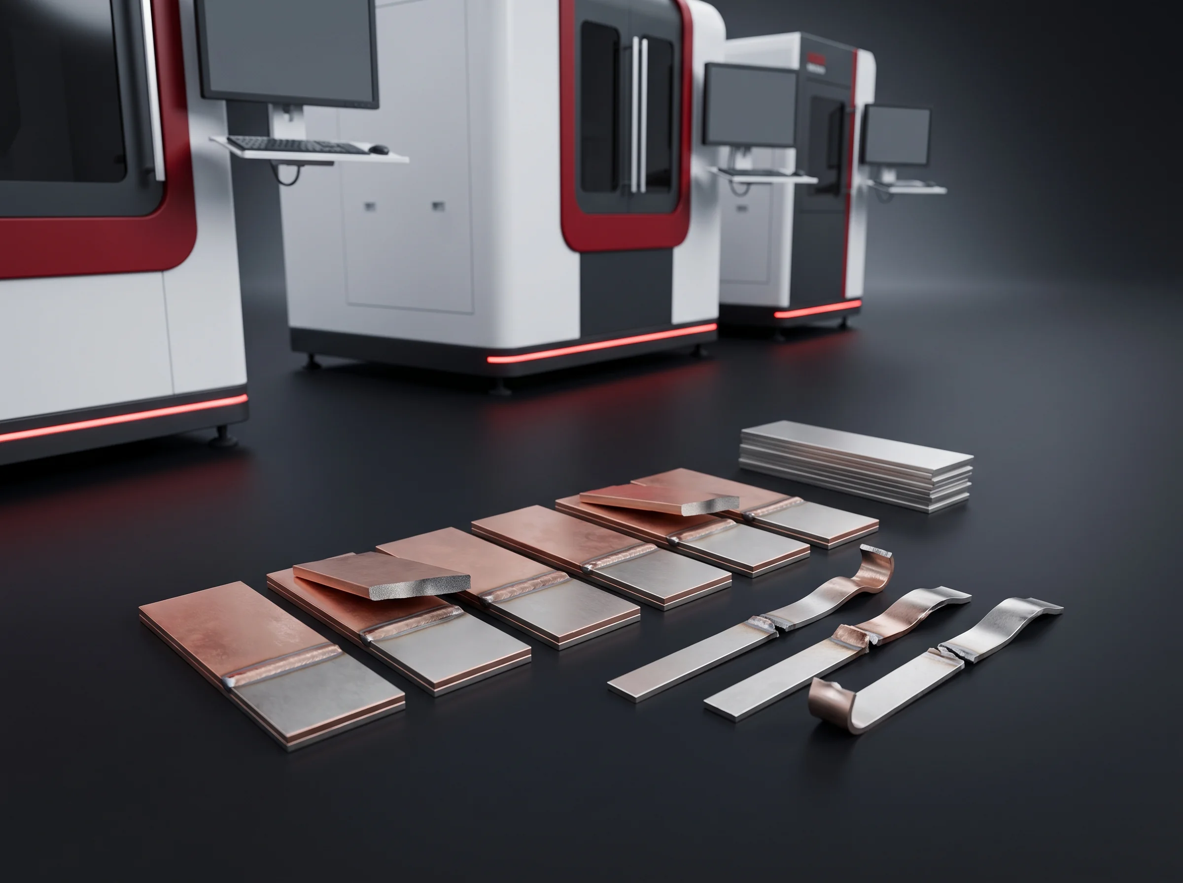
First articles and process trials
Before a joint has a recipe, somebody has to weld it repeatedly and section the samples. Done inside a line, that costs you the line. Done here, it costs you a machine that was standing still.
Repair and rework
A module that failed a downstream check cannot travel backwards through a line: carriers run one way. On this table it is clamped, welded back to the recipe stored under its own part number, and returned to the flow.
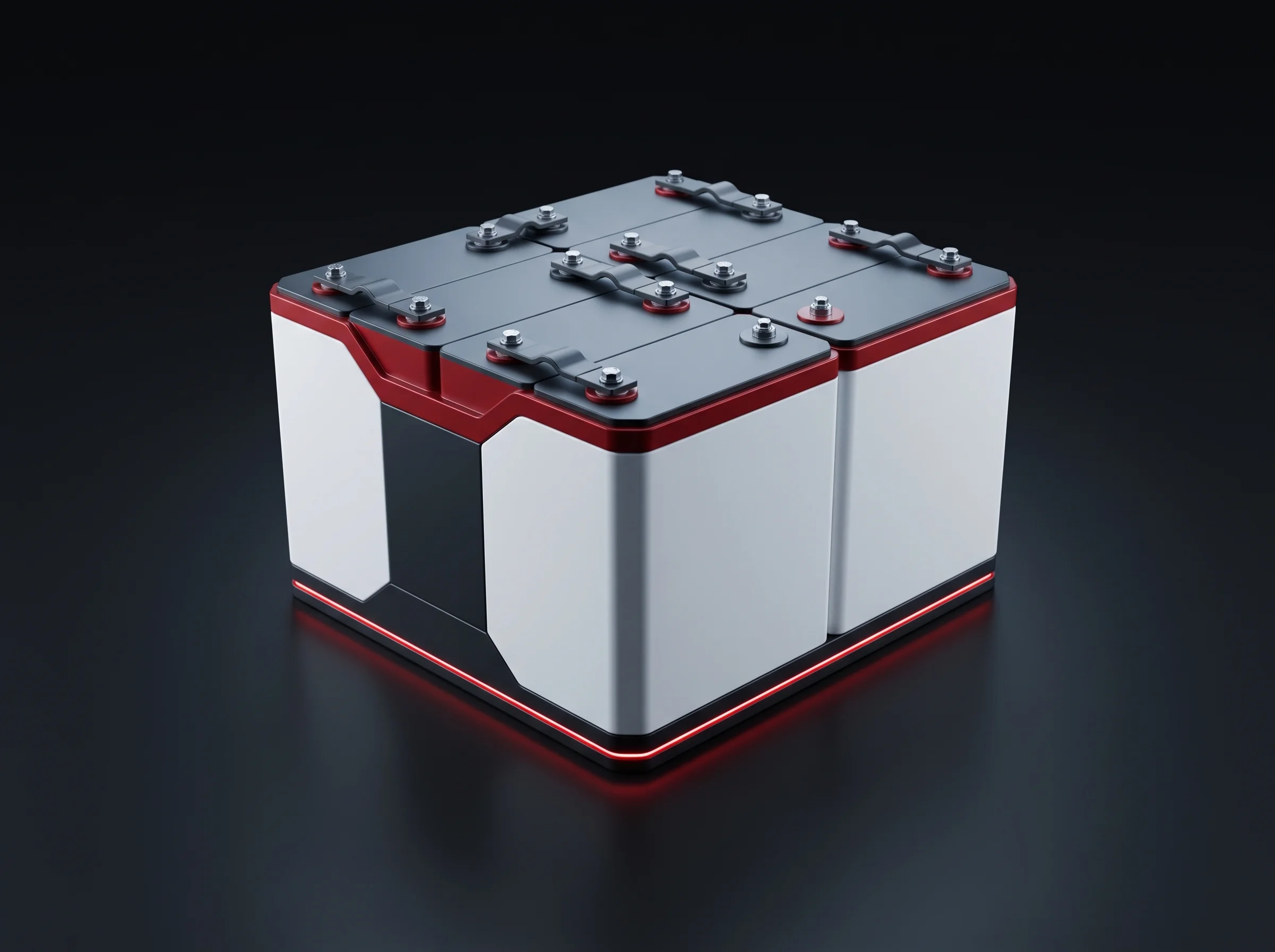
Short runs and outsize parts
Sample builds, spares, brackets, a variant somebody promised a customer, parts longer than an in-line carrier presents to a fixed station. Too small for tooling, too real to refuse.
- The line never stops for any of the three
- The part is clamped to a fixture, not carried in
- The parameters come from the recipe stored under the part number
Five figures the machine is quoted on, before any of them is recalculated against your part.
- 1070 nmWavelength ±10
- ±0.01 mmRepeat positioning
- 4–6 PPMReference part rate
- 10–25 kWPower draw
- 4 × 2 mFootprint
Every figure, one table
The Gantry Laser Welding Machine Datasheet
Items fixed at order are marked — those cannot change on your floor afterwards. Everything unmarked is a setting, a range or a delivered dimension.
| Item | Figure | Status |
|---|---|---|
| Wavelength | 1070 ± 10 nm | Fixed |
| Source power | 1000 / 2000 / 4000 / 6000 W | At order |
| Fibre core diameter | 14 / 20 / 50 / 100 µm | At order |
| Power adjustment | 10–100%, stability within 3% | Setting |
| Repeat positioning | ±0.01 mm | Machine |
| CCD positioning | ±0.01 mm, optional | At order |
| X travel | 800 or 1000 mm | At order |
| Y travel | 400 or 600 mm | At order |
| Z travel | 200 or 400 mm | At order |
| Rate | 4–6 pieces per minute on the reference part | Per part |
| Footprint | 4 × 2 m, ancillaries counted in | Delivered |
| Power draw | 10–25 kW | Range |
| Supply | 380 V / 50 Hz | Plant side |
| Cooling | External water chiller | Separate |
| Ambient temperature | 5–45 °C | Building |
| Machine envelope | 1400 × 1200 × 2000 mm or 1600 × 1400 × 2000 mm | At order |
Seven rows you cannot revisit
Source power, fibre core, the three travels, CCD positioning and the envelope are all decided when the machine is built. A different power means a different source, and that is a machine change rather than a setting.
The three travels come as a frame size rather than as a menu, and the two envelope entries are those frame sizes as delivered.
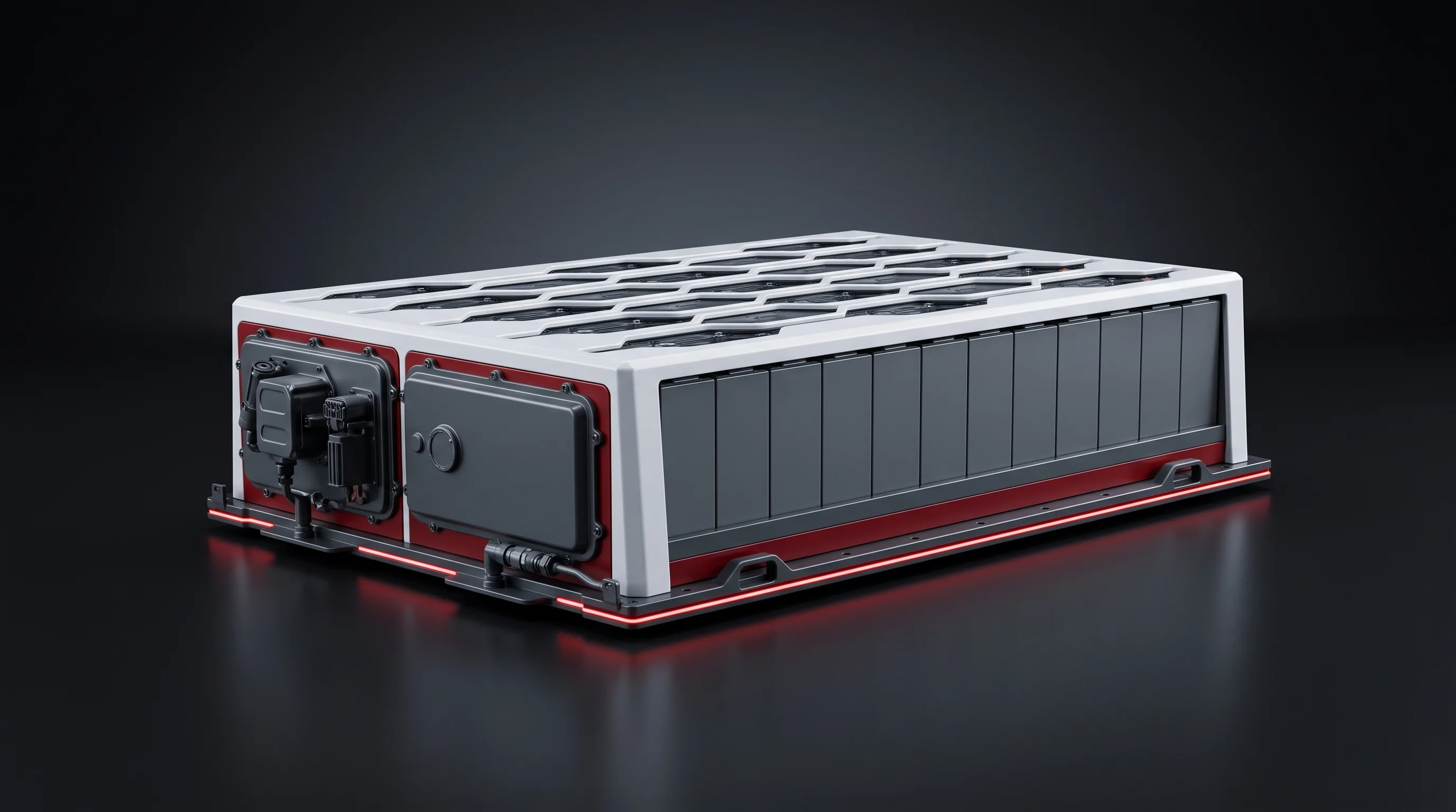
Off the line, or in it
Two Ways A Part Arrives
Both routes weld the same joint. They are quoted, sited and staffed differently, and the rest of this page follows from it.
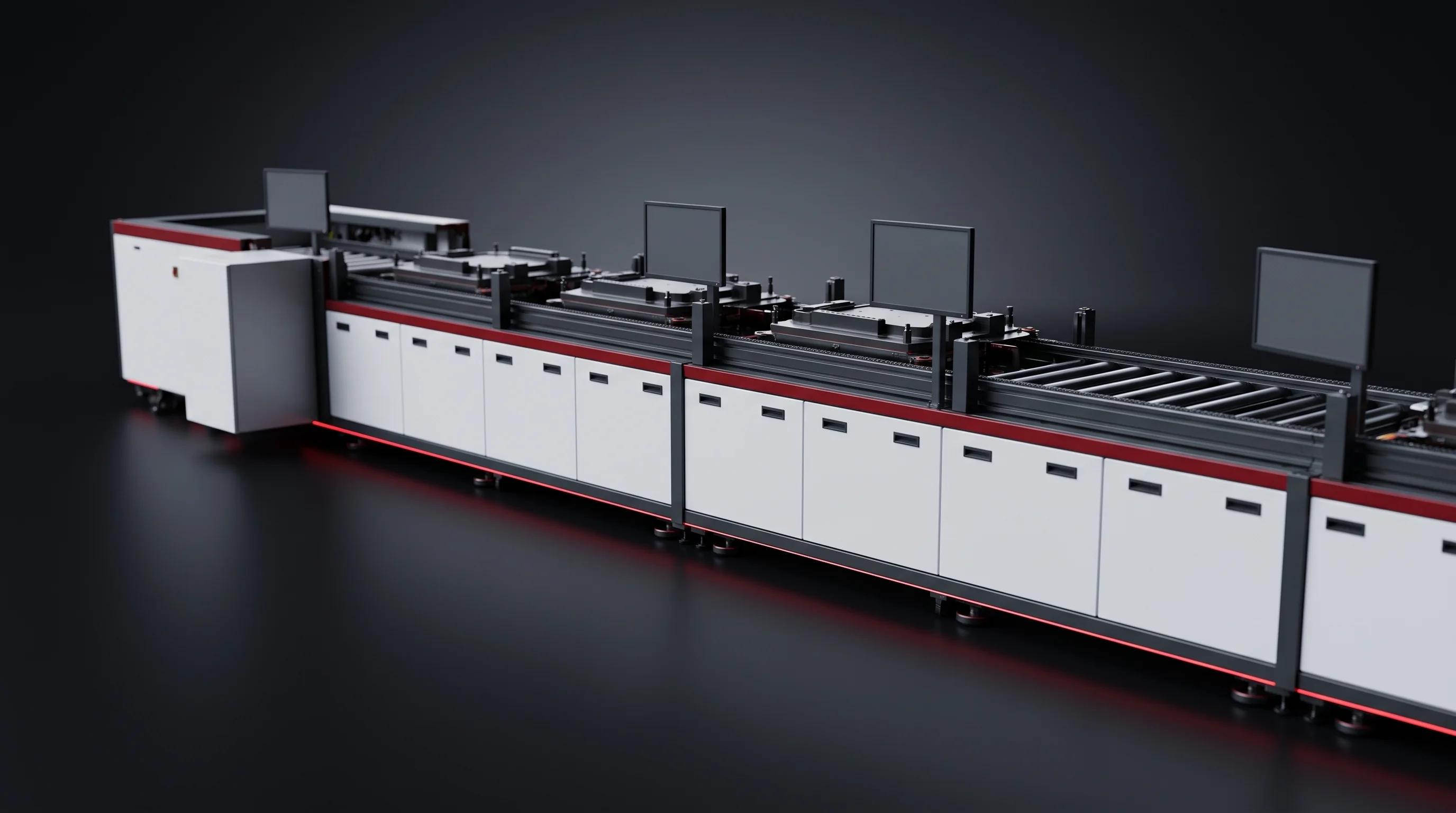
In a line
On this table
- Inside the takt → the in-line busbar welding station, and our reply says so
- On a table → this machine, with the frame size and the rate calculated on your part
The rate
Four To Six Pieces Per Minute
One rate figure on this page, because one reference part sits behind it. Your part gets its own figure, in writing, before you order.
Measured on a defined reference part, set out in full below — the machine's own cycle on that part, clamped by hand at the table.
The reference part, in full
- Clampings
- One
- Total weld length
- ≤ 600 mm
- Joint layout
- Single-row busbar
- Part level
- Module
- Loading
- By hand, at the table
An off-line machine is slower than a line, which is why it sits off the line.
It sounds right and it is not. Our economy tier runs at 4 to 8 PPM, a figure the line pages own, and 4 to 6 sits inside that band. Speed is not what puts this machine beside the line.
Whose number the rate is
A station's rate is a share of your takt, rebalanced whenever the line is rebalanced. This rate belongs to the machine and the part on its table: it does not enter the line balance, and it stays what it is whatever you build around it.
What you get back
Send the joint layout with total weld length, your clamping concept and the quantity you expect per shift. What comes back is a shift output calculated on your part, with the reference part difference shown line by line.
- Shift output on your part, not ours
- The reference part difference, line by line
- That figure, written into the quotation
Four things move that figure on your part. A part with twice the reference weld length and a second clamping does not run at the reference rate, and no arithmetic makes it.
Total weld length
Number of clampings
Re-teaching between joints
Load and unload time
Four Inputs, One Specific Answer
Materials, thicknesses, a photograph or drawing of the joint, and the largest part you clamp. The reply names a source and core pair, a frame size and a rate on your part.
Ordered as a pair
Source Power And Fibre Core
Four power options and four core diameters look like sixteen combinations. In practice, one ordered pair, fixed when the machine is built.
Power sets the ceiling
From 1000 W for thin strip work to 6000 W for heavy busbar sections. The one datasheet item that cannot change afterwards: a different power means a different source, which is a machine change rather than a setting.
Core diameter travels with the beam
A 14 µm core concentrates the same watts into a far smaller spot than a 100 µm core. A source ordered against the wrong core reaches its rated power and still misses the joint you bought it for.
Adjustment, and the one option
Everything downstream of that choice is adjustable: 10 to 100 per cent of the ordered power, held within 3 per cent. CCD positioning is ordered separately, as its own quotation line.
| Item | Decided | Changeable later |
|---|---|---|
| Source power | With the fibre core, at order | No — a different source |
| Fibre core diameter | With the source, at order | No — ordered as a pair |
| Power percentage | In the stored recipe | Yes, 10–100% within 3% |
| CCD positioning | Its own quotation line | No — ordered or not |
Two figures, two meanings
Repeat Positioning At ±0.01 mm
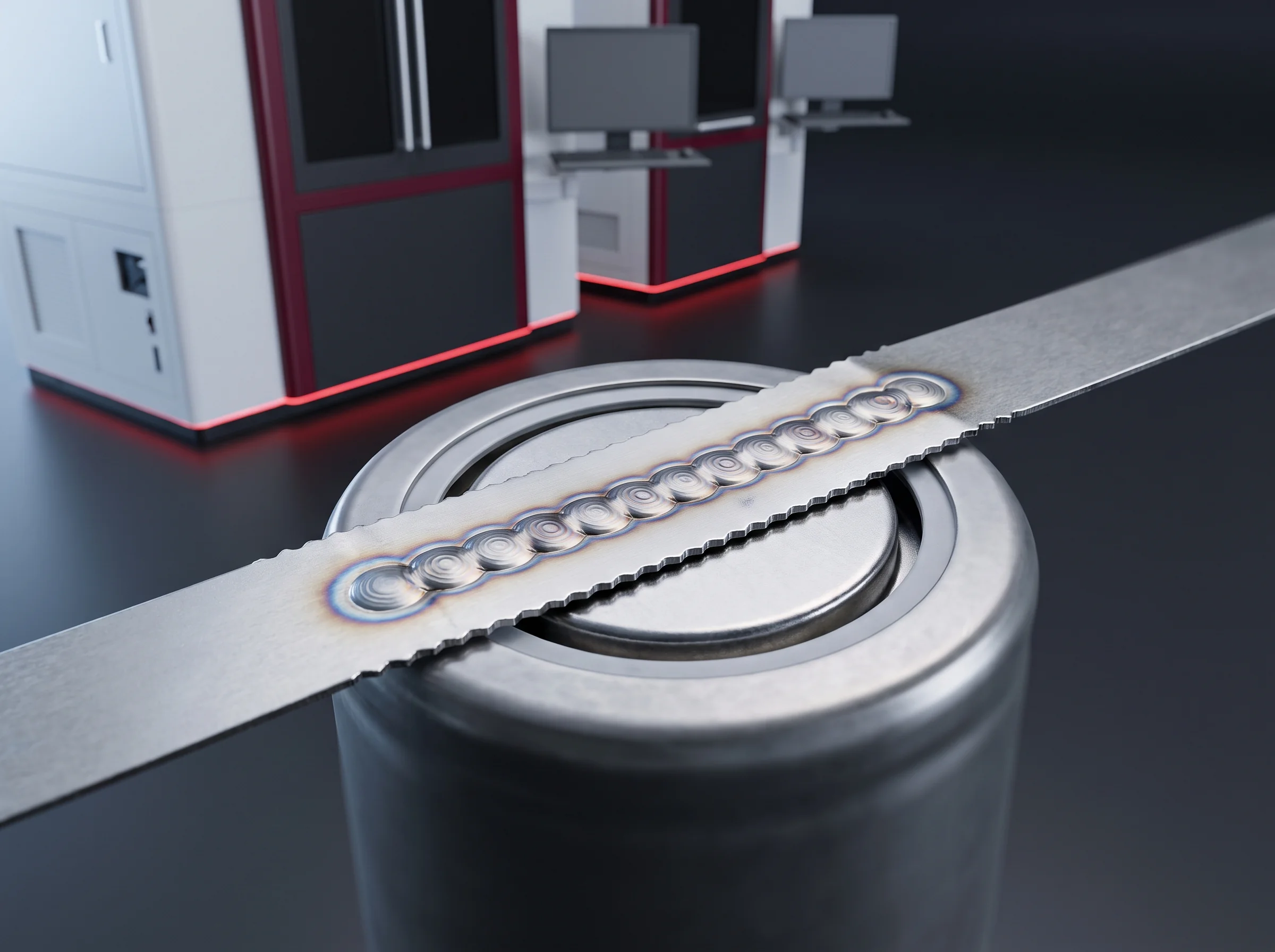
Two datasheet rows read ±0.01 mm and measure different things. Repeat positioning is where the head returns against the machine's own datum. CCD positioning, an ordered option, finds a feature on the part in front of it.
Three kinds of work pay it back
Thin nickel strip
In the 0.1 to 0.3 mm range used on cylindrical and consumer packs, weld width is in the same order as part thickness. A head that wanders a tenth of a millimetre welds off the strip rather than onto it.
Terminal-area joints
On the line, terminal addressing works to ±0.2 mm before a busbar is welded — an order of magnitude coarser, and a different job. Small welds near a post are where the finer figure does its work.
First articles
The least obvious of the three. When you weld the same path forty times to section the samples, repeatability is not a convenience, it is the property under test — forty samples of forty slightly different processes is not a trial.
Between the machine figure and your finished joint sit your fixture and your part tolerance. Two identical machines holding parts in two different fixtures produce two different results, and that gap is closed with hardware, not with numbers on a page.
The factory check record
Taken before the machine left our floor.
The CCD line in the quotation
Stated explicitly, so the option is on paper before the machine is built.
The commissioning measurement
Position and width criteria for your joint, measured with your part in your fixture and written into the acceptance document.
The recipe route
One Recipe Set, Two Machines
Welding parameters here are stored by part number, not by operator. A busbar geometry, or a bracket and strip specification, has one recipe.
Operators select the part number and run it. They do not edit it, and this is not a place where new parameters get invented on a night shift.
The route into the line
A first article welded here produces a candidate recipe, and the three steps below carry it into the in-line BLP-W6 station unchanged. The process engineer sets it, quality signs it, on both machines alike.
Rework runs the same way in reverse: a module that comes back for repair is welded to the recipe already stored under its original part number, so the repair was made with the parameters the batch was qualified on.
One part number, one recipe
Power percentage, travel speed, focus offset and shielding gas — stored against the part number, selected rather than typed.
What you receive
- A recipe table indexed by part number, operator access limited to selection
- First-article samples with their pull-test record, carrying both signatures
- Rework work orders naming the recipe they called
First article, on this table
Welded repeatedly under a new part number, samples sectioned.
Pull-tested against the published criterion
Tested against the criterion the in-line station publishes, and both signatures go on.
Into the in-line station unchanged
Same format, same fields, same two signatures. A trial on this table is a trial done for your line, not next to it.
That path across two machines is why we quote this welder as part of a plant rather than a box on a floor. How we work generally is on the about page.
Will it hold your part
Travel, Fixture And Frame Size
Travel is the outer bound of the work area, not the working area. The fixture takes its share from inside it, and Z covers the part plus whatever holds it down.
The arithmetic settles the frame size on its own. Our blueprint module measures 978.4 mm long, a figure owned by the cell compatibility and changeover page. A module of that length clears the 1000 mm X travel and does not fit the 800 mm one. The blueprint pack at 1152 mm clears neither.
That makes BLP-WG a part-level and module-level machine, welding before the pack is closed.
- Blueprint module, 978.4 mmX 1000 mmClears
- Blueprint module, 978.4 mmX 800 mmDoes not fit
- Blueprint pack, 1152 mmEither frameDoes not fit
Y and Z settle it too
The travels are ordered together as a frame size, so a part that clears X but not Z has already decided which frame you buy.
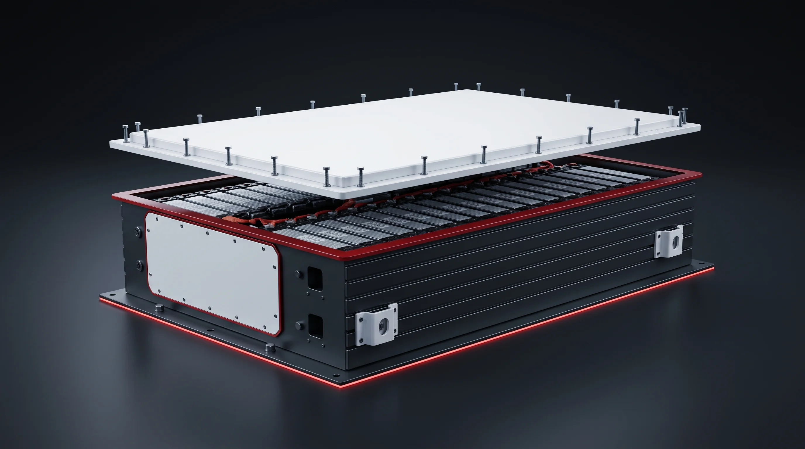
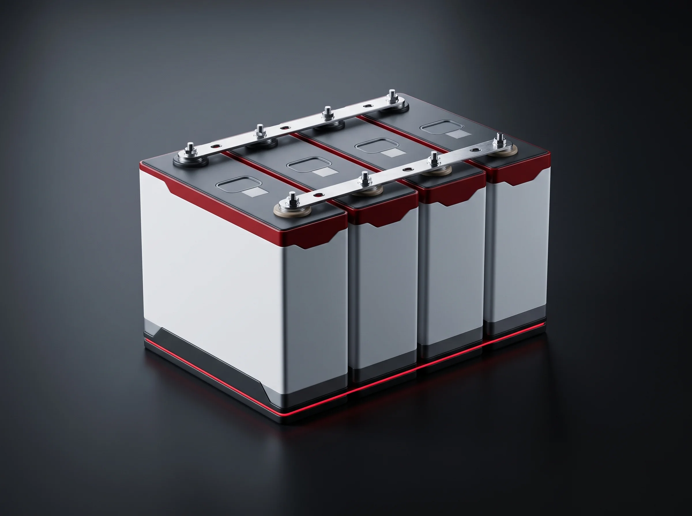
- Busbars, connectors, brackets and strip work — inside both frames
- Complete modules within the travels
- A closed pack is past this machine and belongs in the line
Two frames
The Two Machine Envelopes
Ordered as a frame size, delivered as a rectangle
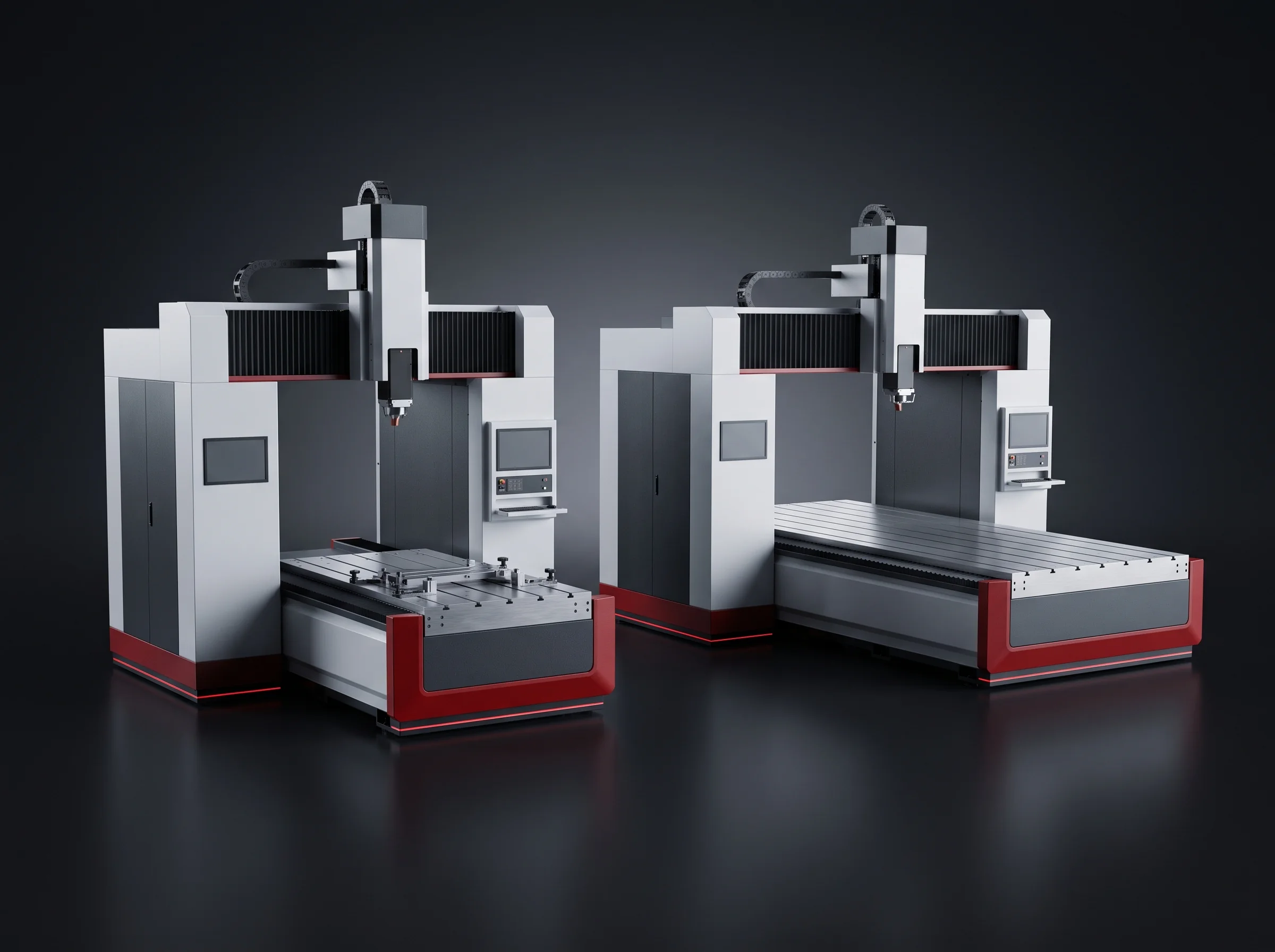
The travels are ordered as a frame size, and these are those frame sizes as delivered — the rectangle and the height that go on your layout drawing.
Both stand 2000 mm tall, so the difference is table width and travel, not headroom. Neither figure includes the external water chiller, which takes its own floor area beside the machine.
| Frame | Envelope, mm |
|---|---|
| Smaller | 1400 × 1200 × 2000 |
| Larger | 1600 × 1400 × 2000 |
On your layout drawing
Gantry Laser Welding Machine Footprint
Machines of this kind are often quoted as a bare frame, with the cabinet and service loop turning up later as somebody else's problem. Here the figure is the one you draw.
The footprint is 4 × 2 m with the laser ancillaries counted inside it. The external water chiller stands separately, with its own floor and service access, and belongs on the layout at the same time.
It draws 10 to 25 kW on a 380 V / 50 Hz supply — the standard our lines run on, so a plant already fed for a line has nothing new to arrange. Ambient temperature is 5 to 45 °C, a specification about your building rather than the machine.
On the drawing
Plant-side services for a full line — compressed air, nitrogen and floor loading — are published per tier on the layout and utilities page.
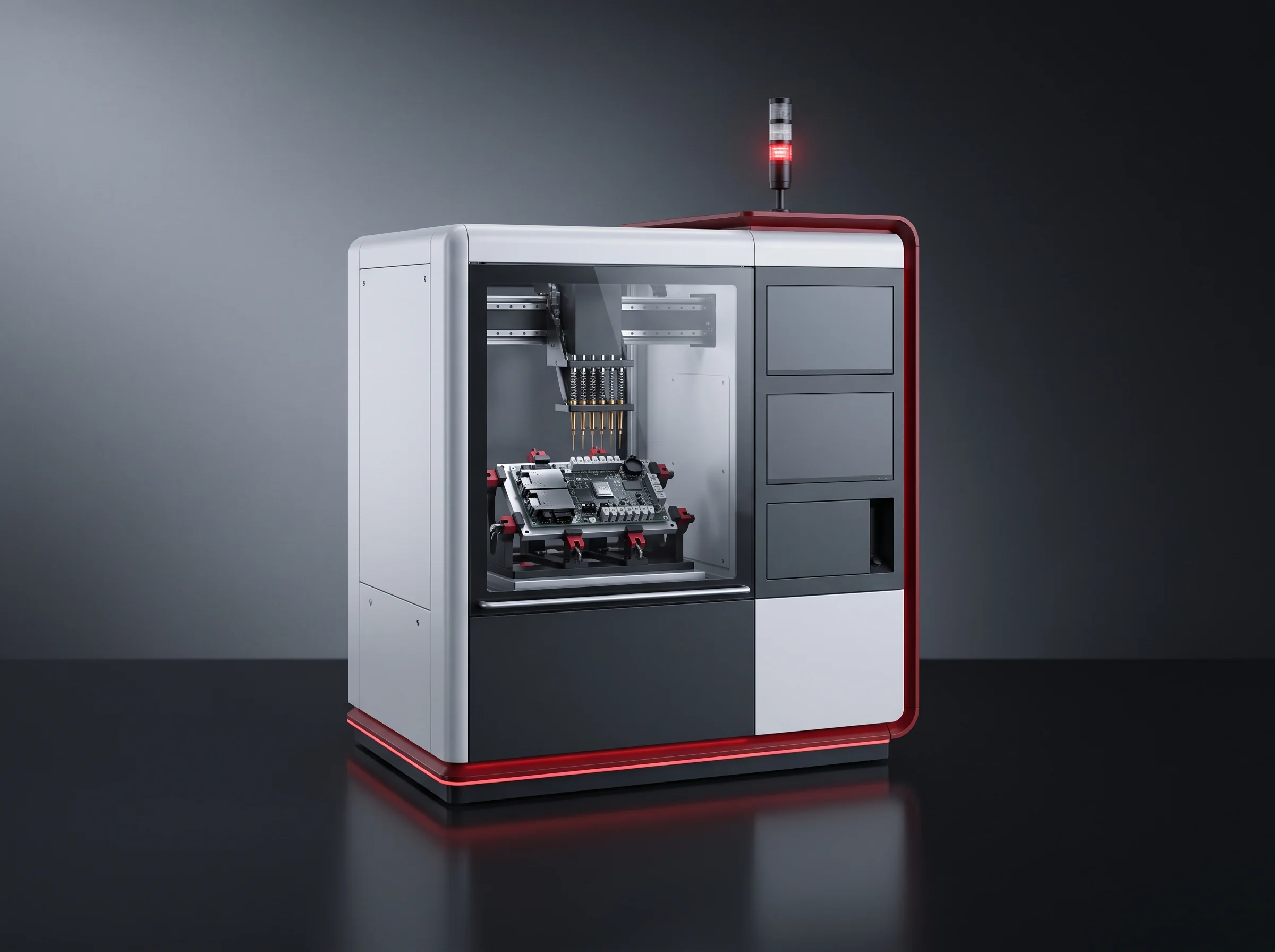
- The rectangle you draw is the one we quoted, cabinet and service loop included
- One 380 V / 50 Hz feed at 10–25 kW
- A second position on the drawing for the chiller, with its service access
- An ambient range of 5–45 °C — a question about your building
Five inputs
Quoting Your Gantry Laser Welding Machine
Four are about your part. The fifth is about what stands behind the machine.
Materials and thicknesses
On both sides. The input that names the source and core pair.
The joint itself
A photograph or a drawing. Weld length and layout are read off it.
Largest part you clamp
With your fixture concept, so the arithmetic includes the fixture.
Rough quantity
Per shift or per week, so the rate becomes an output you can plan on.
What stands behind it
One of our lines, or a line you already own. It changes nothing about the machine and everything about the recipe route.
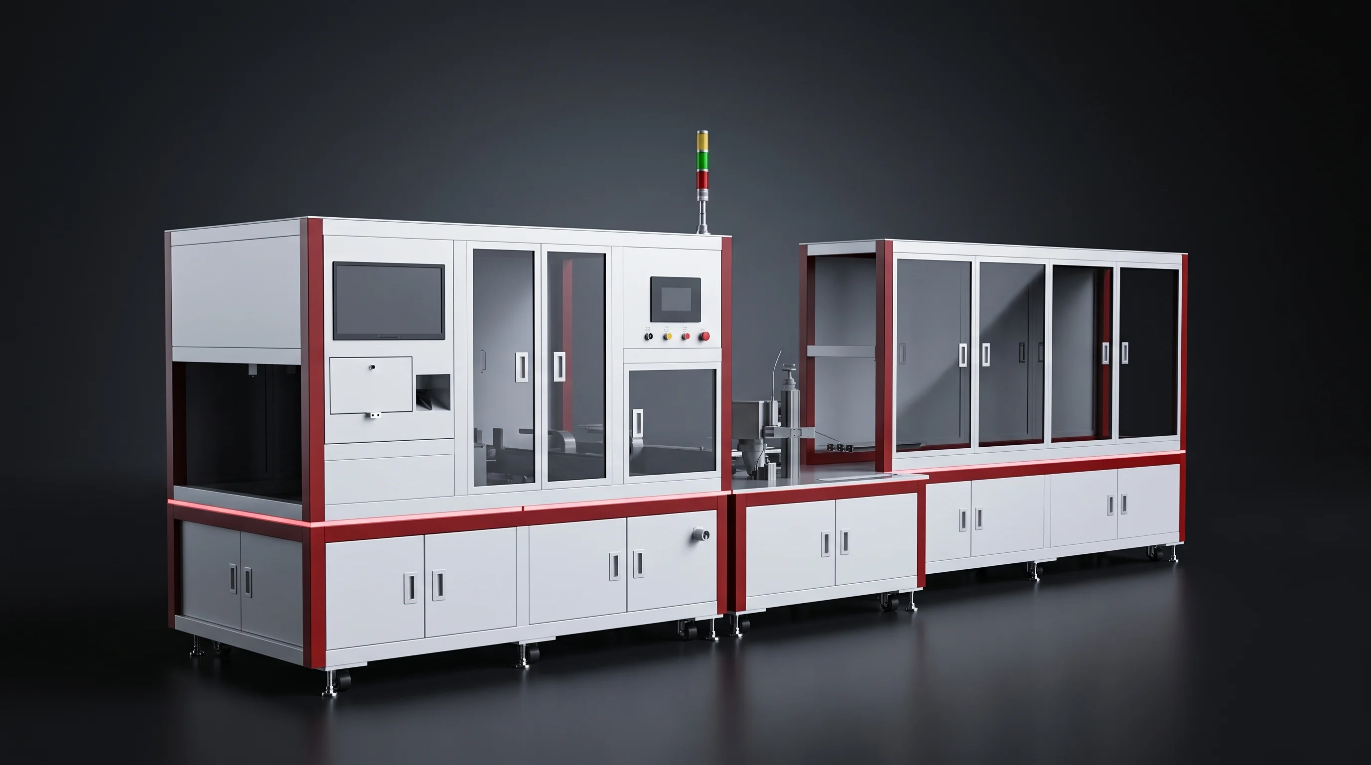
Back within 24 hours
- The source and fibre core pair we would quote, and why
- The frame size your largest part needs, fixture counted in
- Whether CCD positioning is worth ordering
- The rate calculated on your part, not our reference part
- The machine as a line item, chiller and supply shown separately
Your enquiry, ready to send
If your email client opened, it is already in the message. If nothing opened, use one of the two routes below.
Start a project
Send Your Joint And Your Part
Five inputs to our engineering team and the source and core pair, the frame size and a rate calculated on your part come back within 24 hours. Behind it: 26 engineers, a 6,000 m² assembly floor and more than 40 line segments delivered into 12 countries, on the about page.