Cells in at one end, tested packs off the other — one takt across both segments +86 15327155363 [email protected]
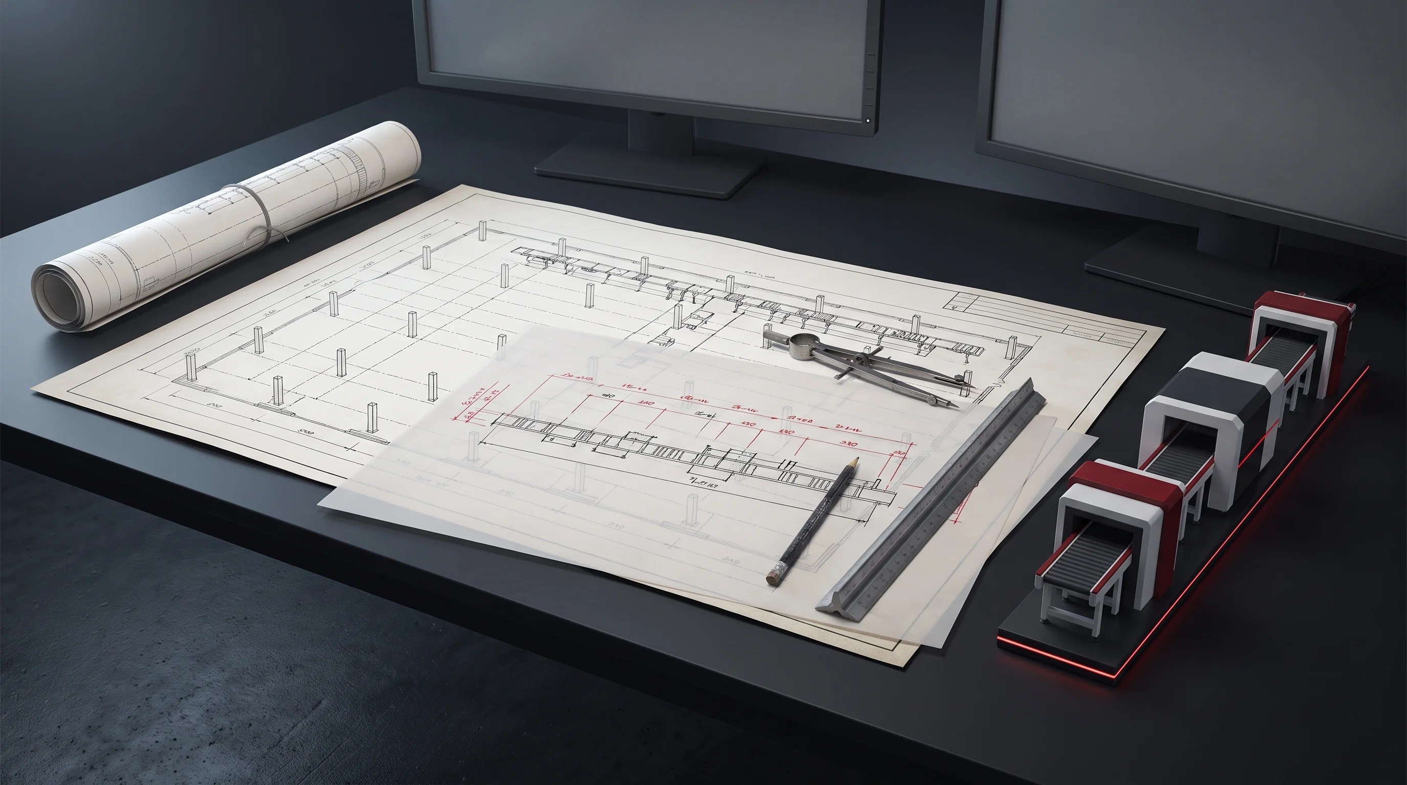
Battery pack line factory layout & utilities drawing on a column-grid floor plan with a red-marked line run

Bay dimensions and utilities

Battery Pack Line Factory Layout & Utilities, Tier by Tier

Battery pack line factory layout & utilities are stated at the interface to your building: the clear height, floor loading, 380 V supply, compressed air and nitrogen each of the three line tiers draws, and a layout drawn to your column grid rather than issued as a standard drawing. Send bay length, width and clear height to the lowest obstruction; the tier answer and a layout drawn into your building come back within 24 hours.

380V Three-phase five-wire, ±5 per cent, 50 Hz. Same form on all three tiers.
0.5–0.7MPa Compressed air, 3000 to 5500 L/min by tier.
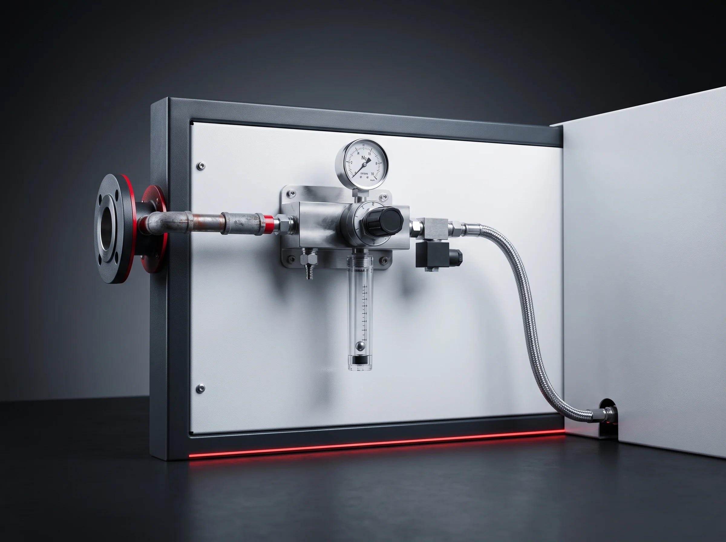
0.5MPa N₂ Nitrogen at the welding stations, 20 to 80 L/min by tier.
≥800kg/m² Distributed floor loading under the run, all three tiers.

Plan · three footprints on one column grid · example grid 12 × 21 m BLP-P15 54 × 20 mBLP-P8S 56 × 10 mBLP-P8 55 × 9 m

ABC DEF 12 12 m21 m span MODULE SEGMENT → PACK SEGMENT HANDOVER BLP-P15 · 54 × 20 m · 12–15 PPM BLP-P8S56 × 10 m BLP-P855 × 9 m 010 m

Three footprints to one scale: length differs by 2 m, width by more than a factor of two. Width is what decides which tier a standing hall takes, and width is the dimension a standing building is least able to give.

One drawing, one schedule

Battery Pack Line Factory Layout & Utilities Drawing

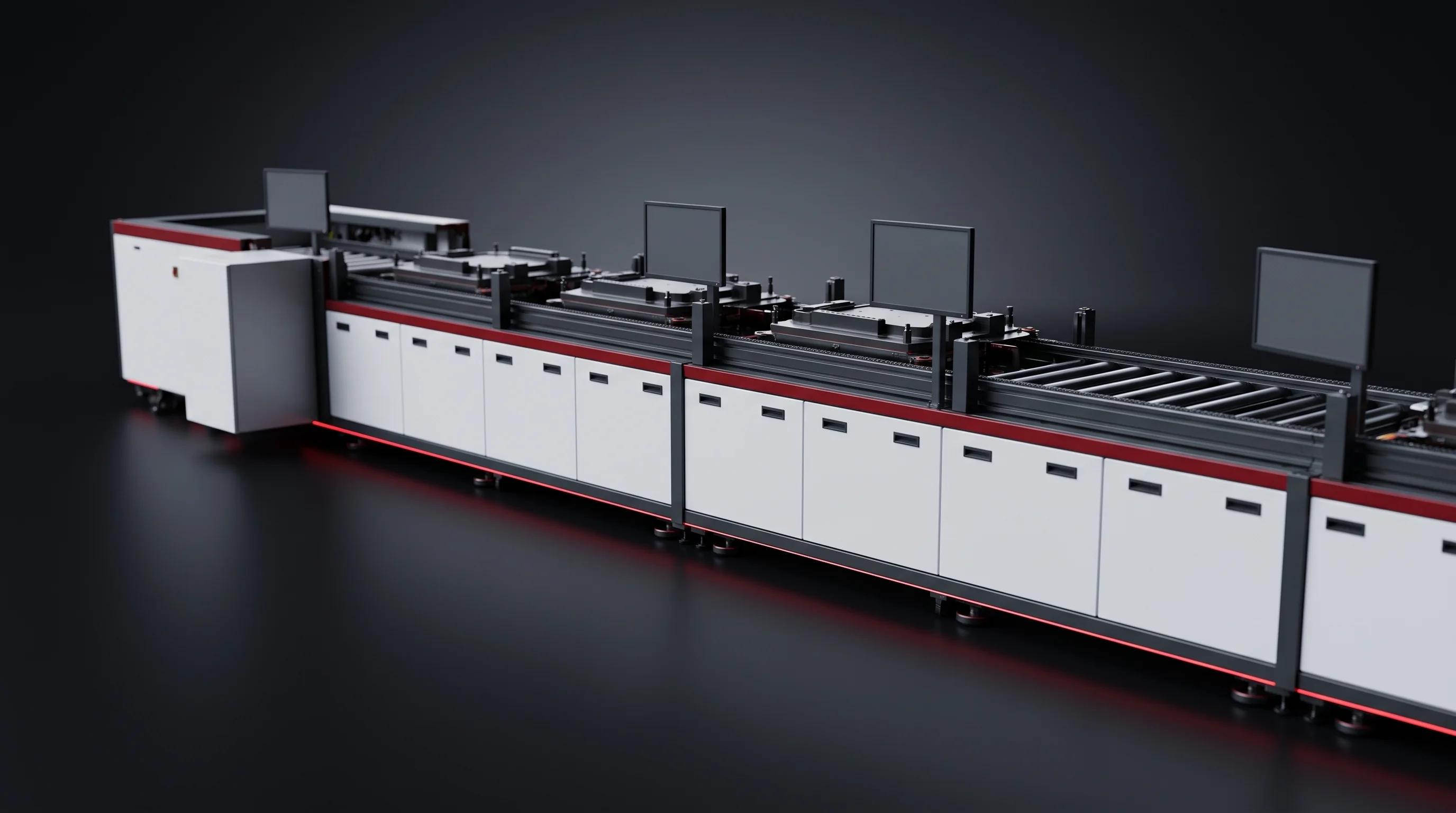
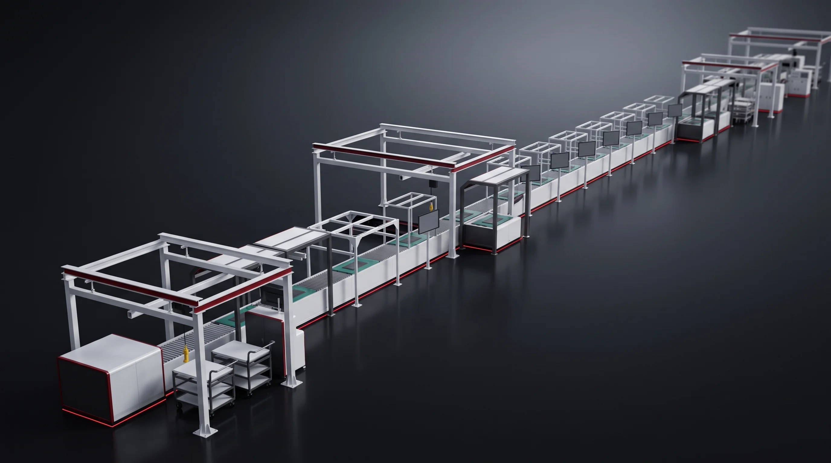
A layout from BatteryLine Pro is drawn against the building you have rather than against a standard hall, and it arrives as one drawing and one schedule. The line begins where finished cells arrive and ends at a tested pack going out; the drawing covers that stretch of floor.

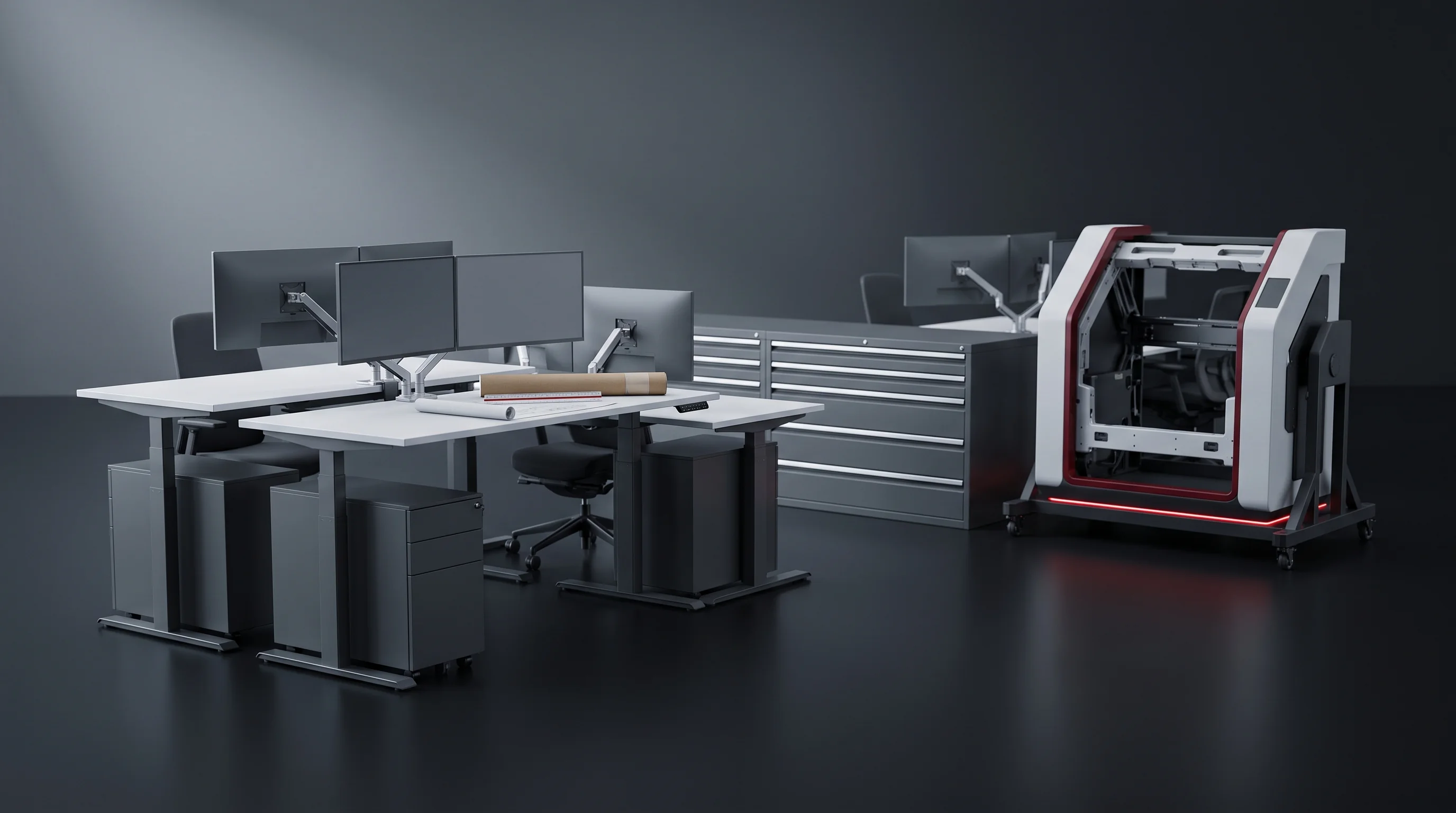
Battery pack line factory layout & utilities engineering office with drawing desks and a gantry welding frame
Drawing

Both segments placed in your bay

The drawing places the module segment and the pack segment in your bay, with all 17 module stations and 15 pack stations in the order they run, the handover between the two segments marked, and the aisles, maintenance faces and loading points where they actually land in your building. What happens at each position on it is on the battery pack assembly line page.

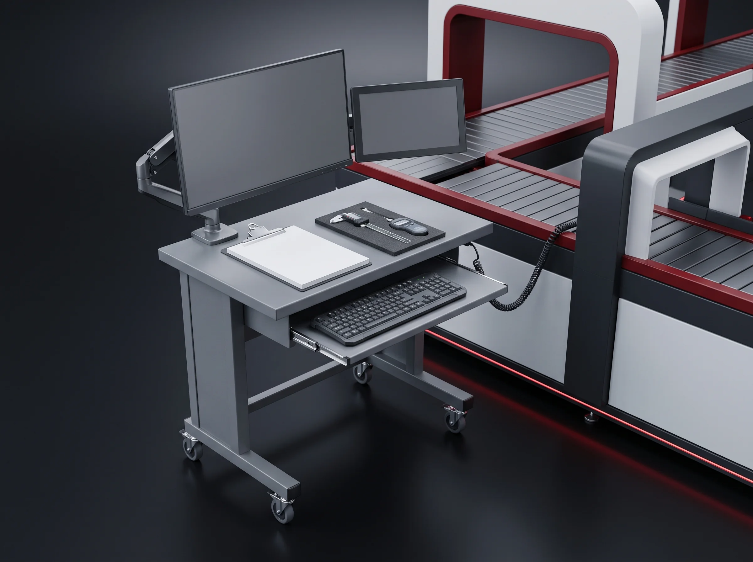
Battery pack line factory layout & utilities schedule on a clipboard at a record desk beside a conveyor
Schedule

Seven rows at the interface

The schedule states what the line draws at the interface to your services for the tier you are quoted: clear height, floor loading, supply, compressed air and nitrogen. Seven rows, one per building figure, and every value is stated at the interface rather than somewhere inside the machines.

Stated and drawn by BatteryLine Pro

  • The figures at the interface, tier by tier.
  • The line drawn to fit the bay, both segments and the handover placed.
  • Footprint dimensions adjusted to the building, which is why the drawing follows your floor plan rather than preceding it.

Specified by whoever owns the system

  • Transformer and distribution board.
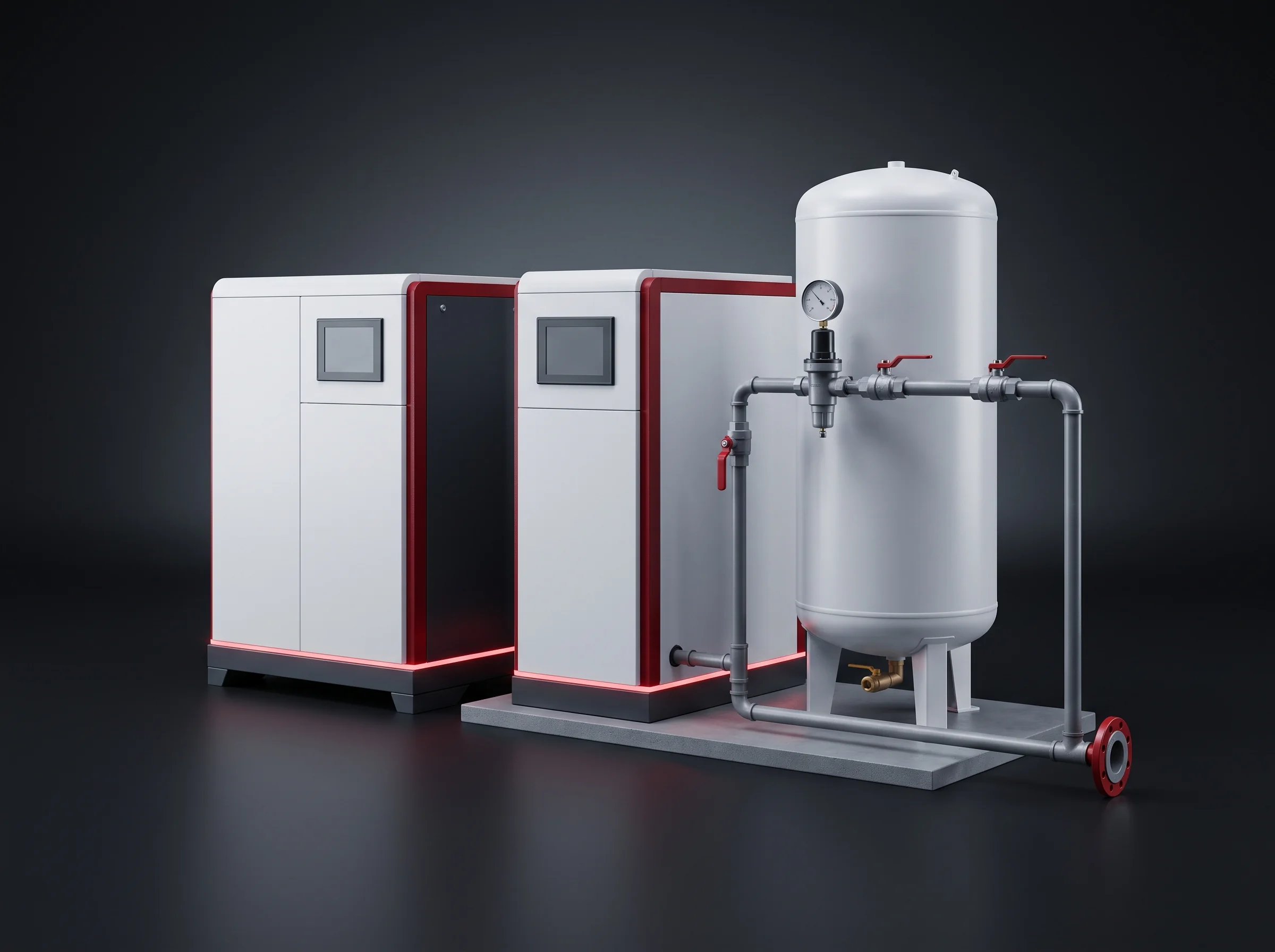
  • Compressor, dryer and receiver.
  • Nitrogen source: cylinder bank, dewar or generator.
  • The slab itself, against the loading figure below.

Clear height

Clear Height to the Lowest Obstruction

The three tiers need 4 m, 3.5 m and 4 m of clear height, and clear height is measured to the lowest obstruction over the line route rather than to the underside of the roof.

ROOF STRUCTURE · BEAM UNDERSIDE AT 4.0 m CABLE TRAY · SPRINKLER MAIN · DUCT · CRANE RAIL · 300–500 mm USABLE HEIGHT ALONG THE RUN SLAB · ≥800 kg/m² MACHINE ENVELOPE LID LIFTS · GUARDING · SERVICE ACCESS 4 m 3.5 m 4 m P8SP8P15 4.0 m to the beam 3.6 m to the tray
The same hall measured two ways. To the roof it clears all three tiers; to the tray it clears one. The service layer figures are an example of what commonly hangs under a beam, not a specification.
  • 4 mBLP-P8S economy
  • 3.5 mBLP-P8 standard
  • 4 mBLP-P15 high automation

Lighting, sprinkler mains, cable tray, ducting and crane rail sit below the structure and commonly occupy 300 to 500 mm, so a bay quoted at 4 m to the beam can leave 3.6 m of usable height along the run where the line stands.

BLP-P8 at 3.5 m is the standard build, not a cut-down one

It is the build that fits under a low beam line. Above the machines is working space rather than spare space: guarding, enclosure lids and the service access that keeps maintenance a task rather than a shutdown all live in the height above the machine envelope.

What to send

  • The height to the lowest thing in the way, together with the run of the bay that height applies to.
  • Where the low points differ along the hall, each of them marked on the plan.
  • The layout is then drawn around them, with the tall stations placed in the bays that carry the height.
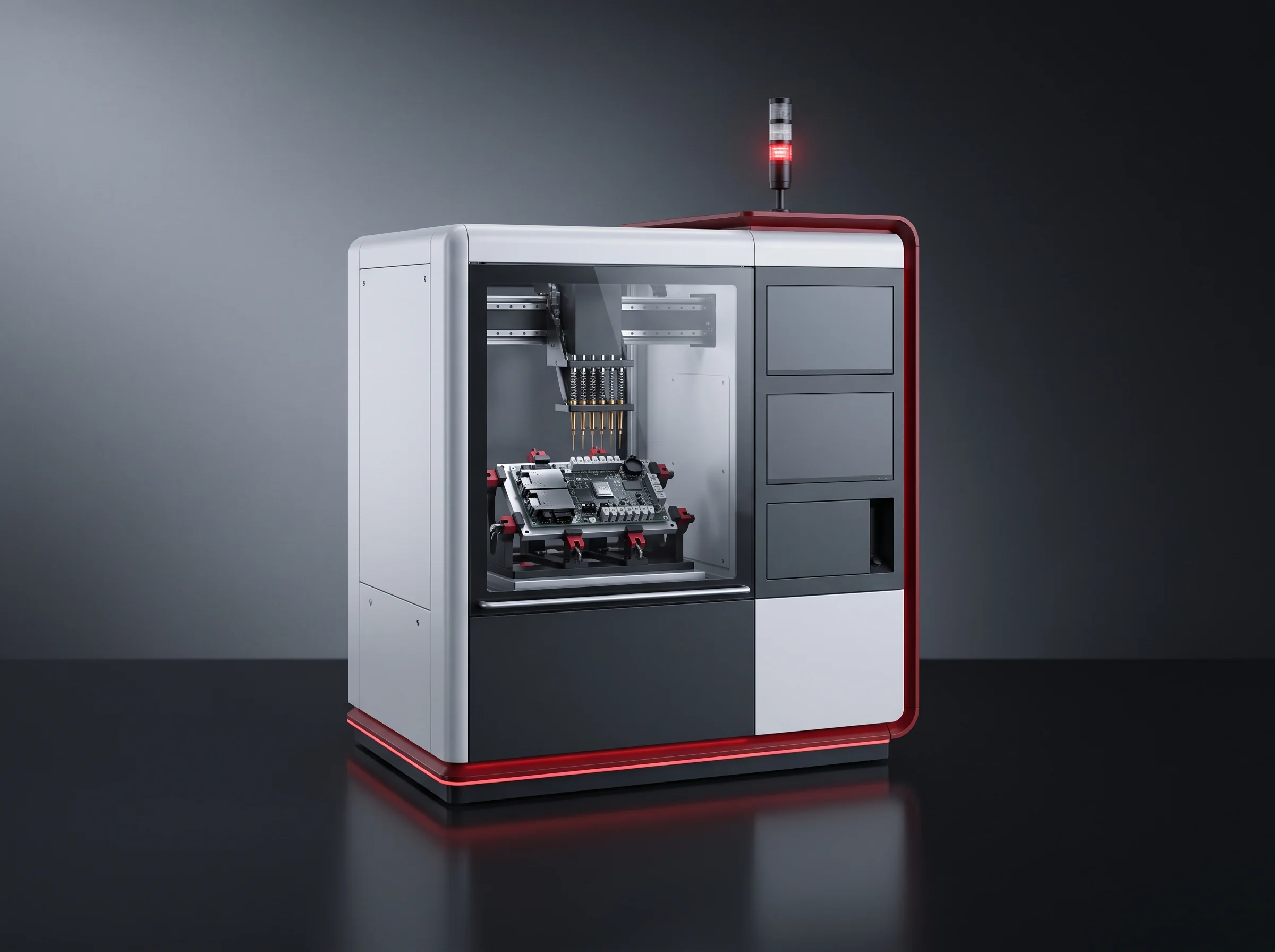
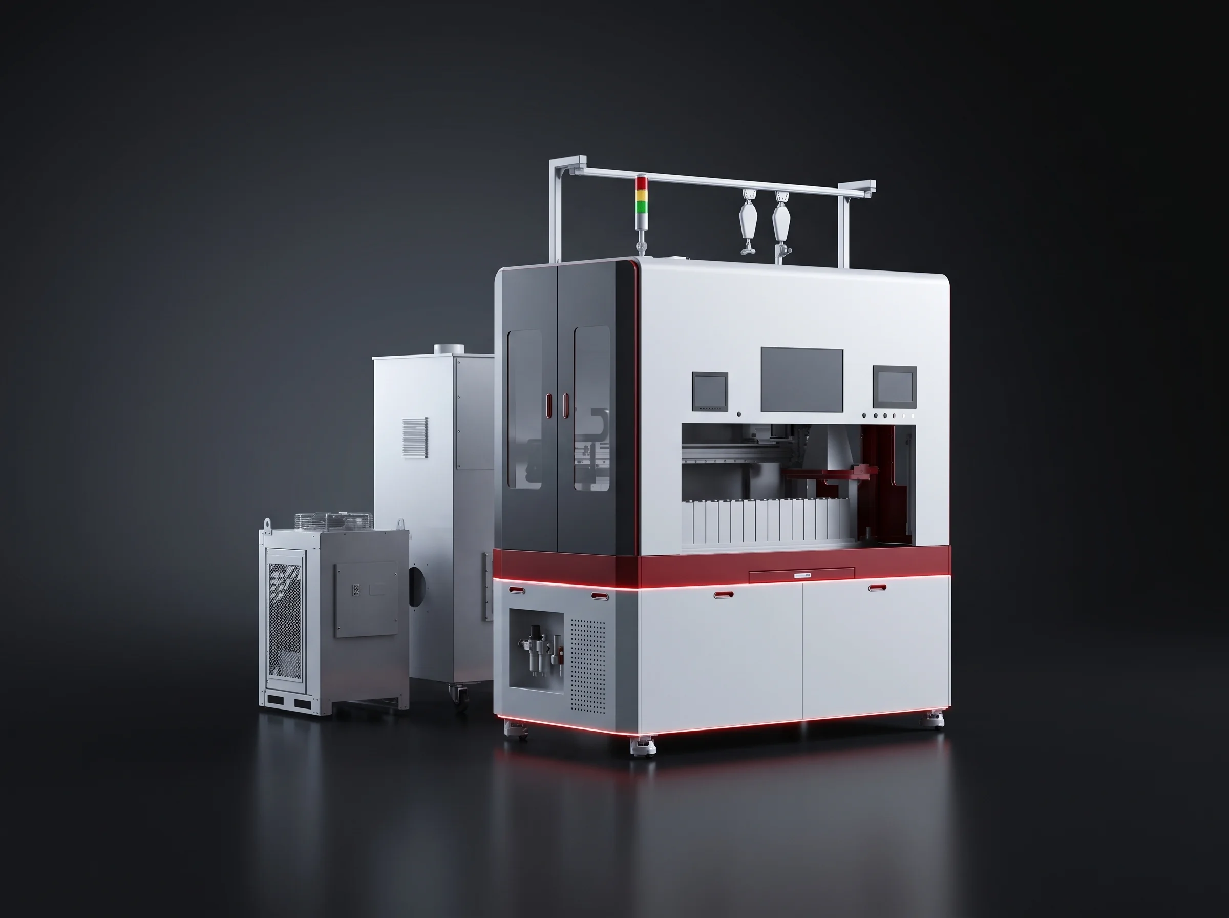
Tall enclosed module end-of-line test station with a lifting lid, placed under the bay that carries the height
A tall station goes under the bay that carries the height; its lid and guarding live above the machine envelope.
Enclosed dispensing station with service access above the machine envelope
Service access from above keeps maintenance a task rather than a shutdown.

Floor loading

Floor Loading Under the Run

≥800 kg/m²distributed, all three tiers, on the strip of floor the line stands on

It applies to the strip rather than the hall average: machine frames, carriers, the modules and fixtures riding on them, and the tooling around each position. Load along the run is spread rather than concentrated: the module conveyor carries modules on their fixtures at 200 kg or more per position, and the weight over the pack segment is what your own handling places there.

Four local problems worth catching early

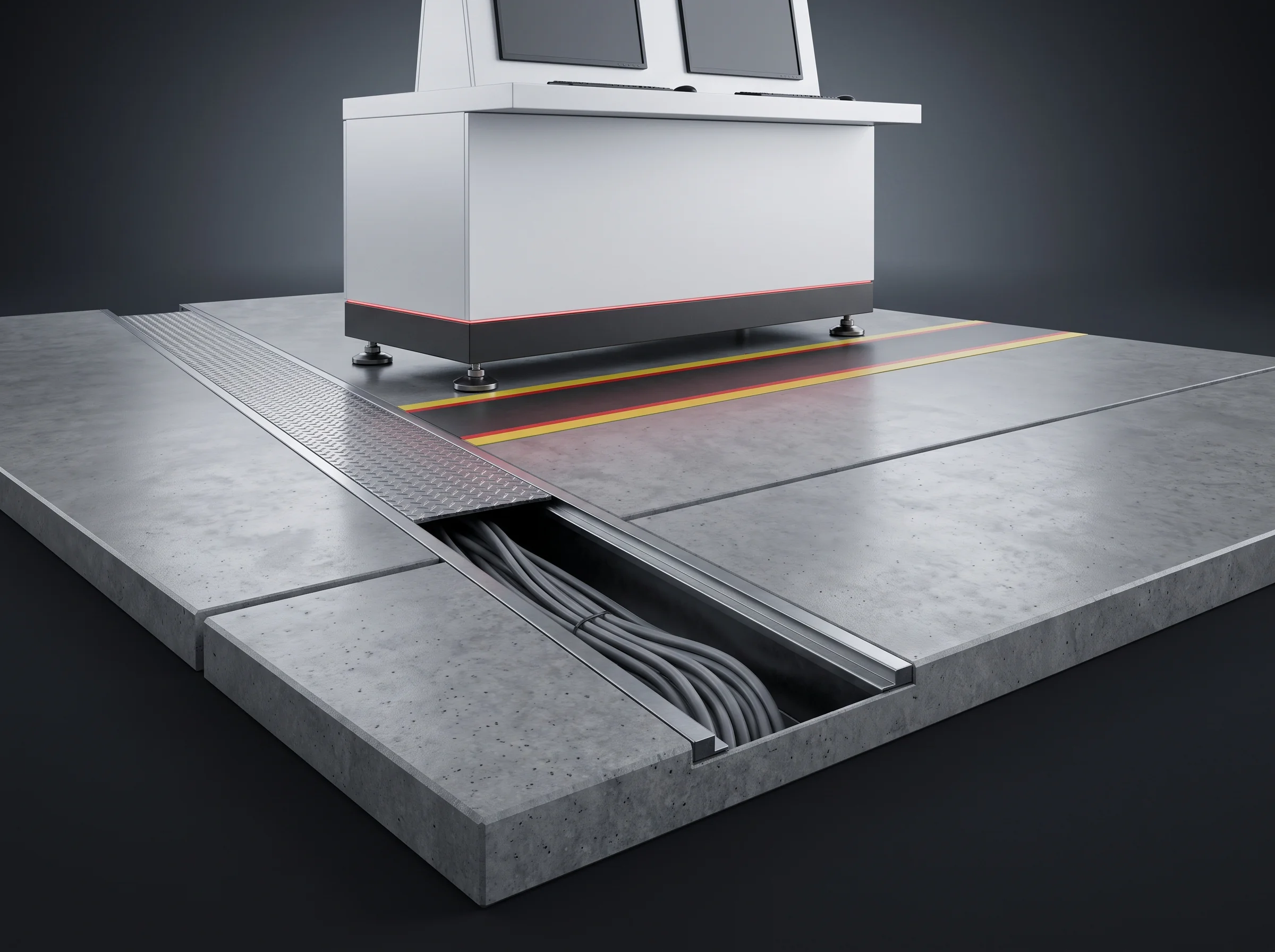
A cable trench crossing the runSits inside a hall that meets 800 kg/m² everywhere else.
An inspection pitAnswered on a drawing in an afternoon, or on site with a saw.
An expansion joint under a machine baseA base cannot straddle a joint; the position moves on the drawing.
The edge of a mezzanineWhere the slab changes thickness, the strip is checked again.

Each of the four can sit inside a hall that meets the figure everywhere else, and each is cheaper on the drawing than under a machine.

Module conveyor carrying battery modules on fixtures at 200 kg or more per position
Image slot: a concrete slab with a cable trench and an expansion joint marked out across a line run

Electrical supply

Three-Phase Five-Wire 380 V Supply

Supply is common to all three tiers: three-phase five-wire, 380 V plus or minus 5 per cent, at 50 Hz. Three properties, and each one is a separate question for whoever owns your distribution board.

5 wires

Neutral and earth arrive separately

  • Adding that to a board built four-wire is straightforward while the floor is empty.
  • Awkward once machines stand on it, which is why it belongs at the drawing stage.
±5 %

The tolerance is part of the specification

  • A supply that sags outside plus or minus 5 per cent under load produces intermittent faults.
  • They surface at different stations on different days.
50 Hz

A 50 Hz line stays a 50 Hz line

  • Drives, transformers and motors along the line are chosen for it.
  • The board has to present it where the line stands.

Installed power differs by tier

  • 200kWBLP-P8S economy
  • ≤250kWBLP-P8 standard
  • 300kWBLP-P15 high automation

Those installed figures are used together with takt, output and headcount to choose between tiers on the battery pack line capacity planning page. What belongs to the building is the form of the supply, which is the same for all three, and whether the board can present it where the line will stand.

Electrical cabinet and laser source enclosure fed at 380 V three-phase
Station control panel on a module pressing station

Compressed air

Compressed Air Flow, Economy Above Standard

Pressure is 0.5 to 0.7 MPa on all three tiers. Flow is not common to them, and the economy line takes more air than the standard line. The mechanism behind that is worth having before a compressor is sized.

  • BLP-P8SEconomy3500L/min
  • BLP-P8Standard3000L/min
  • BLP-P15High automation5500L/min

+500 L/minEconomy above standard. Size the compressor, dryer and receiver against the tier on your order rather than an average of the three.

Image slot: compressor, dryer and receiver in a plant utility room with the line tie-in point
Module stacking and pressing station with pneumatic clamps and stops
Hand-worked cell taping position with air cylinders indexing the parts

A hand-worked position is not an unpowered one

On the economy build more of the flow is worked by hand, and every hand-worked position is full of pneumatics. Each device consumes on every cycle:

  • Parts are clamped pneumatically and located against pneumatic stops.
  • Parts are lifted and indexed by air cylinders.
  • Parts are blown off before assembly and before welding.

The standard build converts part of that motion to servo drives, which draw electrical power continuously and air only where clamping remains. Flow tracks the count of pneumatic devices along the line rather than the automation level of the line.

Two builds paid for in different currencies

Installed power rises through 200 kW, 250 kW or less, and 300 kW. Air runs the other way between the first two tiers: the standard build trades air for kilowatts, and the economy build trades kilowatts for air.
Why the high-automation build sits above both

BLP-P15 has more positions and more transfer between them, and machine-paced transfer, guard interlocks, vacuum and clamping add flow of their own on top of what the remaining hand positions still use.

The 500 L/min shows on the first day every station cycles togetherA compressor sized for the tier below appears at site acceptance and nowhere earlier.

Shielding gas

Nitrogen at the Welding Stations

Nitrogen is supplied at 0.5 MPa on all three tiers. It is shielding gas rather than utility air, and it is consumed where welding happens, so consumption follows how much welding a tier does and how continuously it does it.

CYLINDER BANK DEWAR ON-SITE GENERATOR YOURS TIE-IN0.5 MPa OURS · AT THE INTERFACE BLP-W6 IN-LINEBUSBAR WELDING STATION BLP-WG OFF-LINEFIRST ARTICLES · REWORK
The supply form is a site decision. Any of the three sources serves the line as long as the pressure and flow are present at the connection; the source is specified with your gas supplier.
  • 20–40L/minBLP-P8S economy
  • 40L/minBLP-P8 standard
  • 40–80L/minBLP-P15 high automation

In the line

The busbar welding station is where the gas shields the pool as the gantry and scanner run the joints; the parameters and weld criteria for that station are on the busbar welding station page.

Off the line

The gantry welding machine draws nitrogen when first-article recipes are welded and when a part is reworked to its stored recipe. The high-automation build welds more and welds more continuously, which is why it sits at the top of the three.

Image slot: nitrogen regulator and manifold at the welding station connection
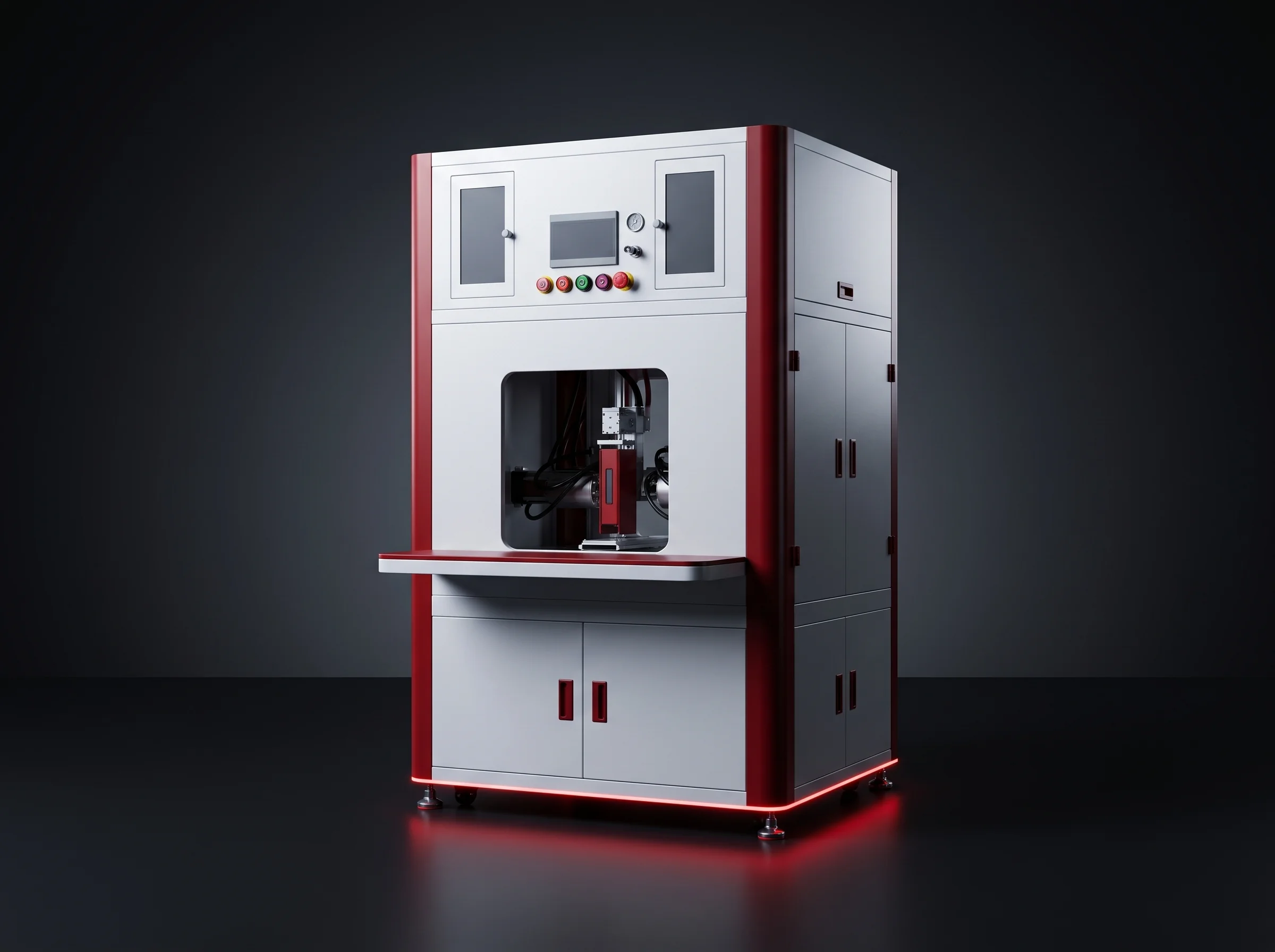
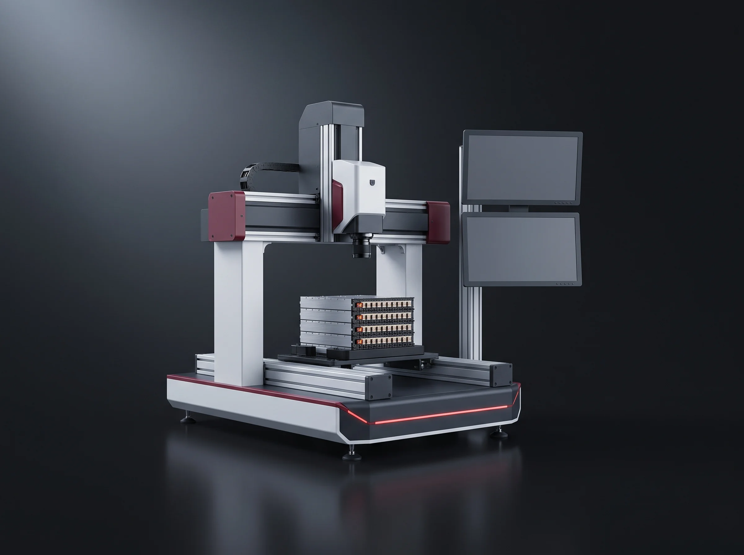
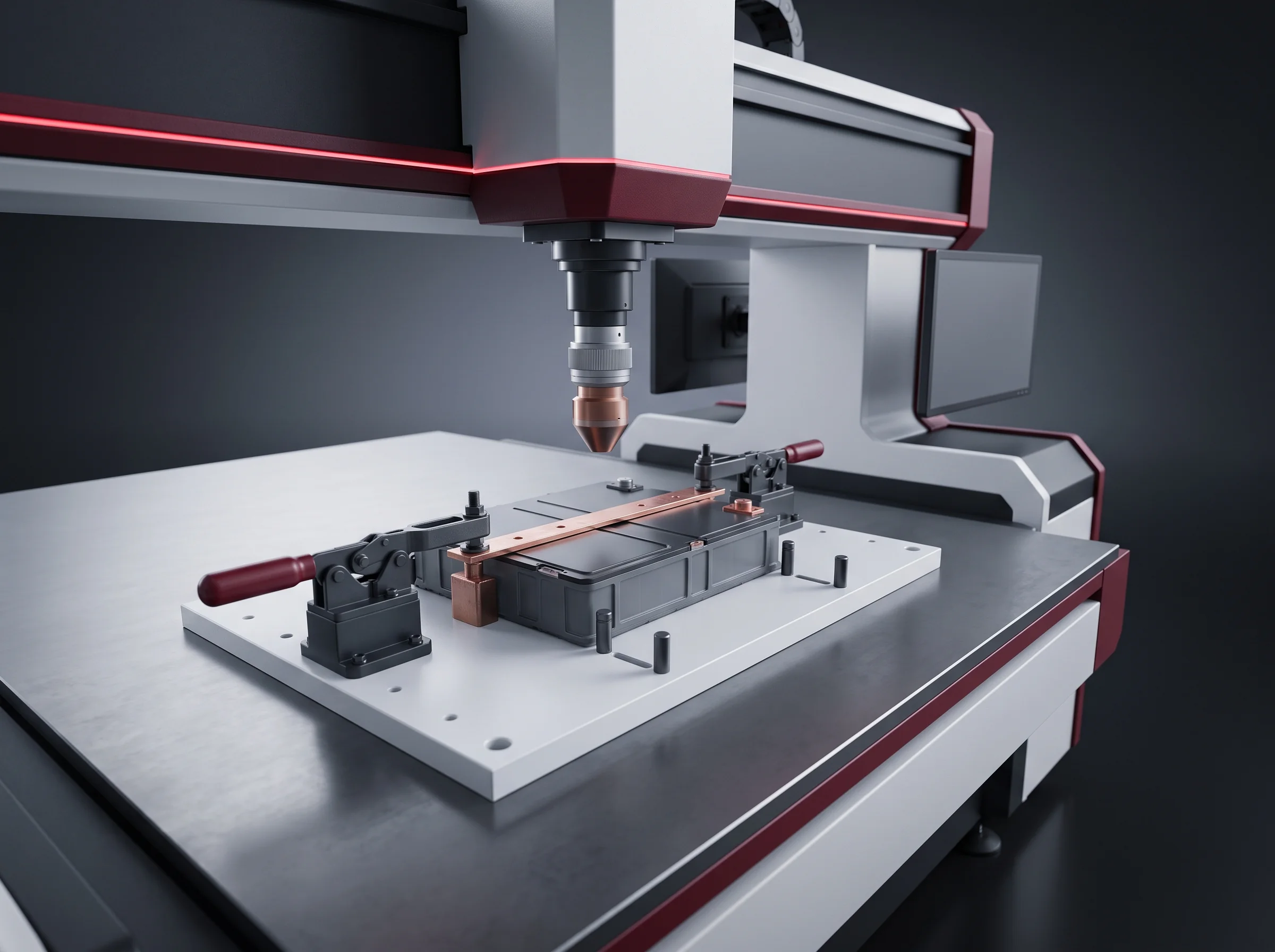
Off-line gantry laser welding machine that draws nitrogen for first-article recipes and rework

Four services, three configurations

Battery Pack Line Factory Layout & Utilities Table

Every building figure for the semi-automatic economy build, the standard build and the high-automation build in one table. Read across each row: three of the seven rows are identical across the tiers, and the two flow rows are the ones that move.

Interface
Battery pack line factory layout & utilities for the BLP-P8S semi-automatic economy line, 56 by 10 metres
BLP-P8SSemi-automatic economy · 4–8 PPM
BLP-P8 standard module and pack line, 55 by 9 metres under a 3.5 metre clear height
BLP-P8Standard · 8 PPM
BLP-P15 high-automation module and pack line, 54 by 20 metres
BLP-P15High automation · 12–15 PPM
Footprint L × W56 × 10 m55 × 9 m54 × 20 m
Clear height required4 m3.5 m4 m
Installed power200 kW250 kW or less300 kW
Electrical supplyThree-phase five-wire, 380 V ±5 %, 50 HzThree-phase five-wire, 380 V ±5 %, 50 HzThree-phase five-wire, 380 V ±5 %, 50 Hz
Compressed air3500L/min0.5–0.7 MPa · economy above standard3000L/min0.5–0.7 MPa5500L/min0.5–0.7 MPa
Nitrogen20–40L/min0.5 MPa40L/min0.5 MPa40–80L/min0.5 MPa
Floor loading800 kg/m² or more800 kg/m² or more800 kg/m² or more

Every value above is stated at the interface to your building. Footprint and installed power appear here as demands the building has to accept; the same two figures are set against takt, annual output and headcount on the battery pack line capacity planning page, where they are used to choose a tier.

  • Layout dimensions are adjustable to the building: the length and width rows describe the configuration as drawn and are re-drawn against your bay.

Every value is stated at the interface to your building.

The transformer, board, compressor, dryer, receiver, nitrogen source and slab stay yours.

FootprintClear heightInstalled powerSupplyCompressed airNitrogenFloor loading

The deciding dimension

Line Width, the Deciding Dimension

  • 10mBLP-P8S · 56 m long
  • 9mBLP-P8 · 55 m long
  • 20mBLP-P15 · 54 m long

Across the three tiers the line is 54 to 56 m long and 9 to 20 m wide, so width is usually what decides whether a hall takes a given tier, and width is the dimension a standing building is least able to give.

  • Length: 54 to 56 m, a spread of only 2 m across the three tiers, and a bay short on length folds.
  • Width: 9 to 20 m, a spread of more than a factor of two, and a bay short on width does not fold its way out.
Cell loading and sorting segment of a module line seen along its width

Straight or folded

Straight Runs and Folded Runs

A bay shorter than the run does not rule the line out; it folds. A folded line runs at the same takt as a straight one, because takt is set at the loading point and by the stations rather than by the shape of the route.

STRAIGHT · BAY LONGER THAN THE RUN MODULE SEGMENTPACK SEGMENT HANDOVER FOLDED · BAY SHORTER THAN THE RUN HANDOVER STAYS STRAIGHT CORNER IN PACK RETURN LEG= TRANSFER + FLOOR+ WALKING DISTANCE
The corner is placed away from the handover, and where a hall gives the choice, the fold goes into the pack segment.

Three things folding costs, all countable on the drawing

  • Transfer between the legs.
  • Floor area for the return.
  • Walking distance for the operators on the segment carrying the most hand positions.

What a fold has to protect

Modules leave the module segment on their fixtures and enter the pack segment at a fixed height and orientation, so the corner is placed away from that handover and the legs are set so the handover itself stays straight. The pack segment tolerates a corner better than the pressing and welding stations do, because its stations are mostly hand positions.

Terminal addressing station on the module segment, kept on a straight leg
Module clamped in its fixture at a fixed height and orientation for the handover

Your column grid

Layout Drawn to Your Column Grid

The layout is drawn to the grid, the height and the openings of your building rather than issued as a standard drawing for the building to match. Four rules govern where things land.

Column spacing sets where segments break and a fold can turn

A machine base cannot straddle a column, and an aisle behind a hand position cannot end at one.

Clear height is taken bay by bay

Tall stations, welding enclosures and anything with a lid that lifts stand under the bays that carry the height; the low bays take conveyor and hand positions.

Doors and aisle turns decide how the line arrives

Door widths, aisle turns and the route from the unloading point to the run are settled on the same drawing as where the line stands.

Equipment already on your floor is drawn in as it is

A press, a rack line or a crane column is a fixed object in the layout rather than something assumed away.

Four inputs, and the first layout comes back drawn into the building

  1. Your floor plan with the column grid and its spacing marked.
  2. Clear height per bay, measured to the lowest obstruction.
  3. The slab notes: trenches, pits, joints and mezzanines.
  4. Whatever stands in the run today.

With those four the first layout comes back drawn into the building rather than beside it.

Two gantry welding enclosures of different size, the tall ones placed under the bays with height
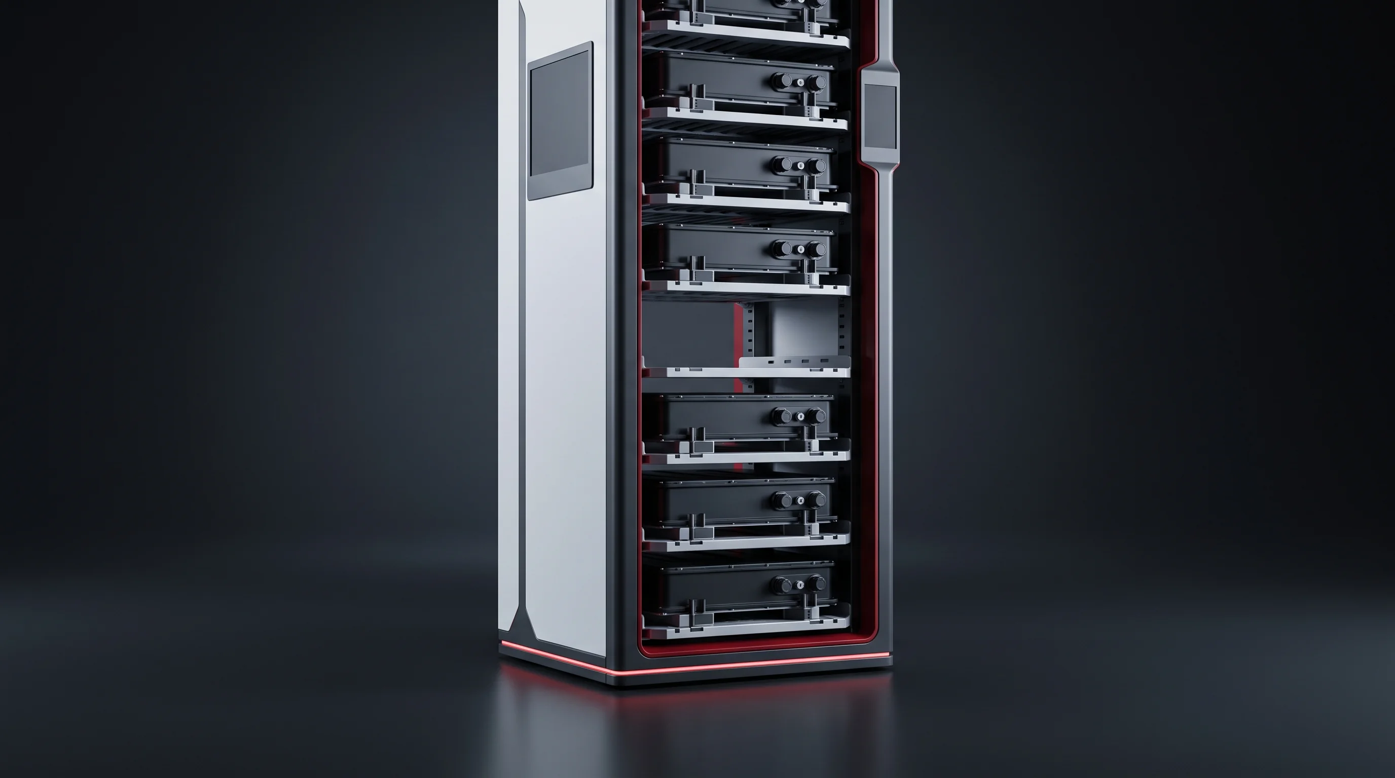
Battery rack cabinet standing on the floor, drawn into the layout as a fixed object

Your bay

Your Bay, Drawn Within 24 Hours

Bay length, width, clear height to the lowest obstruction and the column grid resolve into a tier answer, a layout drawn into your building and a seven-row utility schedule.

Send bay length, width and height
Straight, folded or does not fit Both segments and the handover placed Utility schedule for the tier What has to move first

Single stations

Machine Level Utility Interfaces

The tier figures are line totals. Individual stations carry their own interfaces as well, and those are the numbers that matter when a station joins a line that already exists.

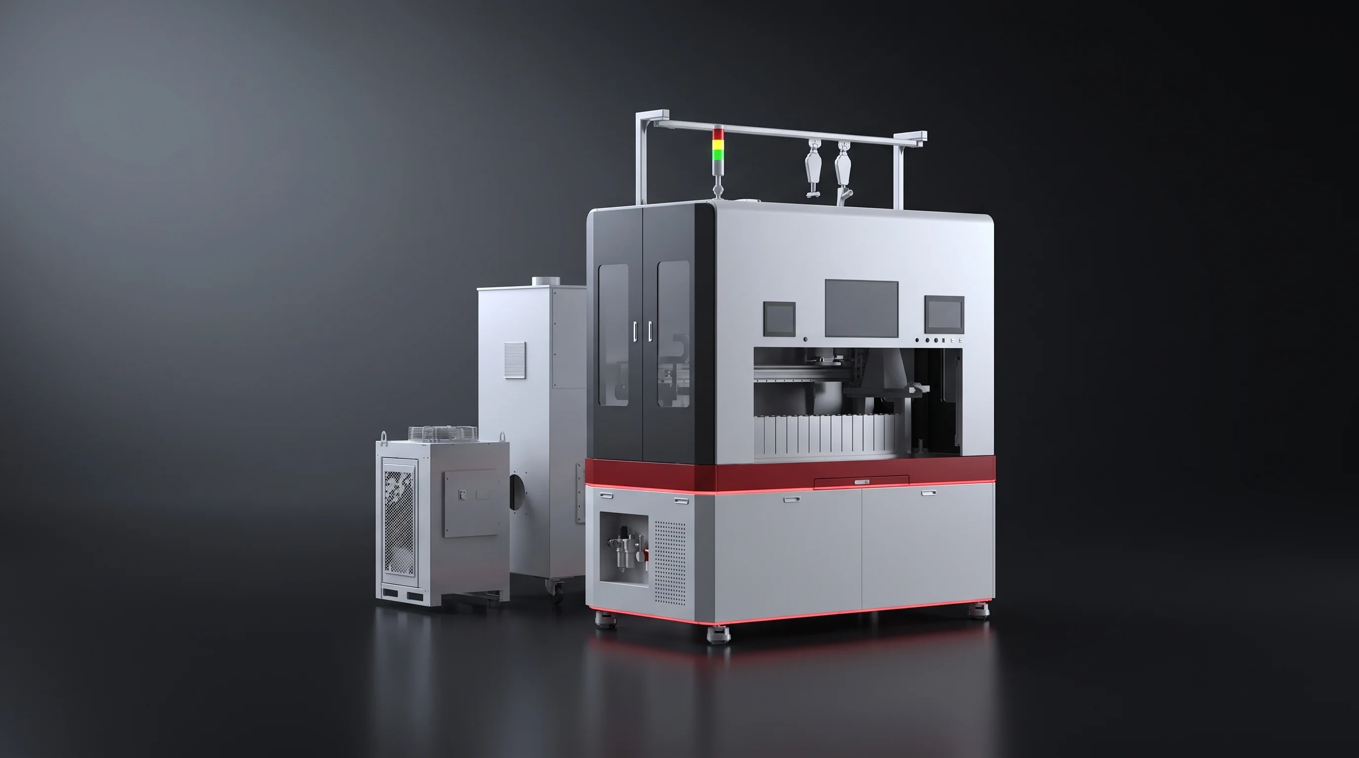
BLP-WG off-line gantry laser welding machine with its laser ancillaries
BLP-WG

Off-line gantry laser welding machine

Floor
4 × 2 m including laser ancillaries
Power
10–25 kW at 380 V, 50 Hz
Cooling
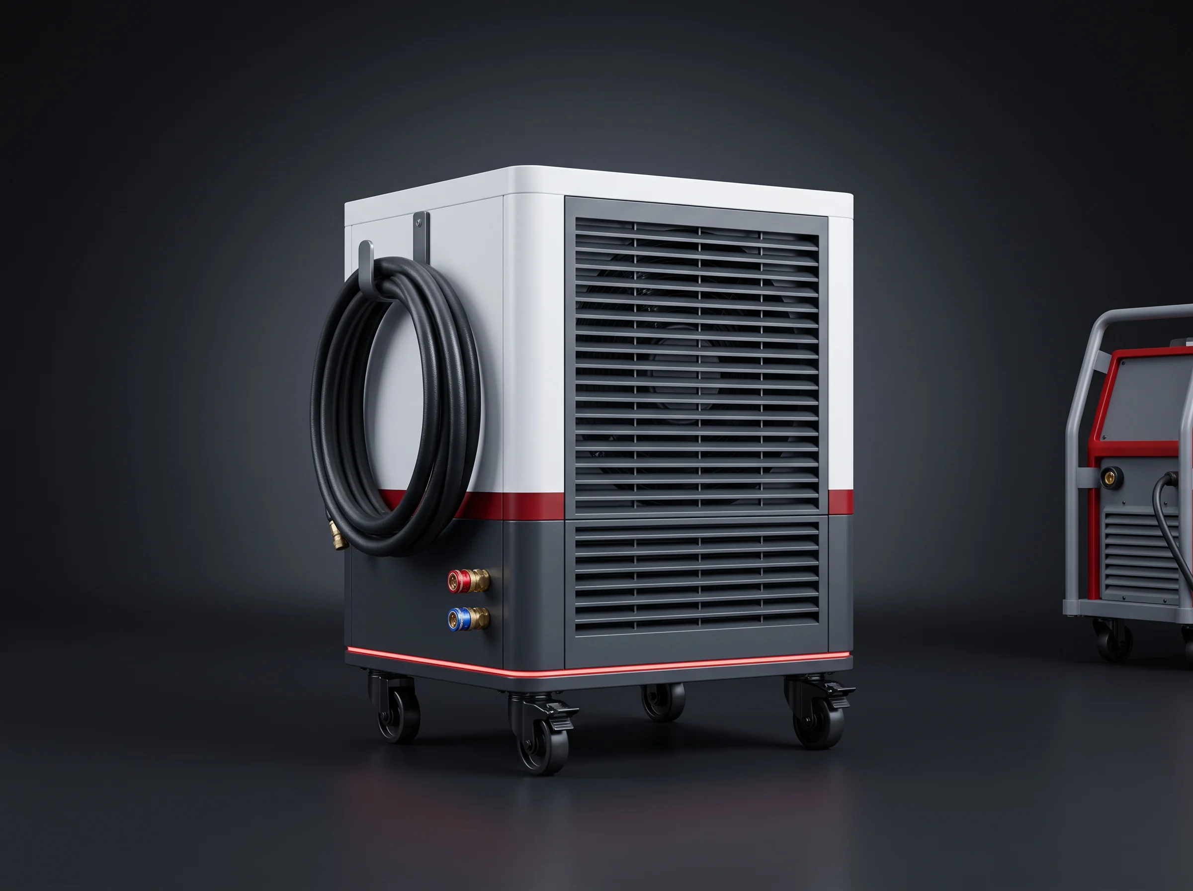
External water cooling
Ambient
5 to 45 °C
Envelope
1400 × 1200 × 2000 or 1600 × 1400 × 2000 mm by axis travel; the height above is service access
External water chiller serving a laser welding machine
Room

Two properties of the room, not the machine

Water
A cooling loop at the machine position, arranged before it stands there
Ambient
5 to 45 °C held where the laser source sits
Why
Both are far cheaper to arrange before the machine stands in the room
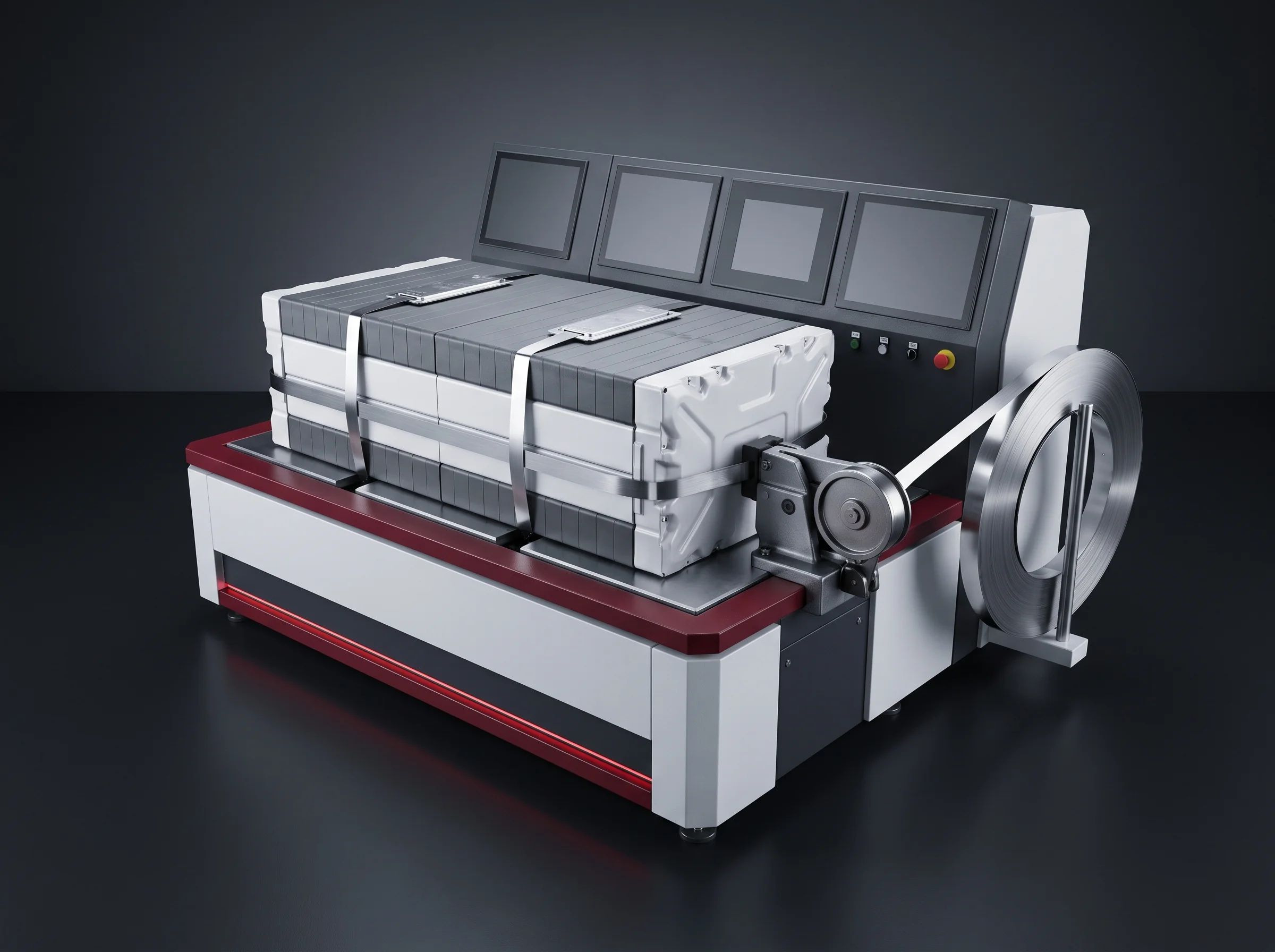
BLP-SP module stacking and pressing station at the steel banding pass
BLP-SP

Module stacking and pressing station

Power
8 kW at 380 V, 50 Hz
Air
0.5–0.7 MPa at 200 L/min or less
Transfer
900 mm ±50 mm, set to match the line it joins
Conveyor
BLP-CV beside it: 200 kg or more per position at 20 m/min or less
Water cooling and the ambient range decide a retrofitBoth are properties of the room rather than of the machine.

Before commissioning

Utilities Live Before Commissioning

Four things are live at the line before commissioning begins rather than during it.

Supply at the boardFive wires at the stated tolerance, presented where the line stands.
Compressed air at full tier flowAt pressure, and at the full flow for the tier rather than a partial supply.
Nitrogen at the welding stations0.5 MPa at the connection, from whichever source the site chose.
A slab cleared along the runTrenches, pits and joints answered; the strip free of what stood there.

Full flow matters because of what site acceptance is

The line runs for 8 continuous hours at the target takt with the rate counted at the loading point, and equipment-caused yield is judged over that run against criteria signed before shipping. It is the first time every station cycles together for a full shift, which makes it the first real test of your air system as well as of the equipment. The acceptance sequence, what each side brings and how a shortfall is retested are on the pack line FAT and SAT acceptance page.

  • Ahead of that the line is assembled and powered up in one of three pre-assembly bays in its shipping configuration, so it reaches your floor having already run as a line.
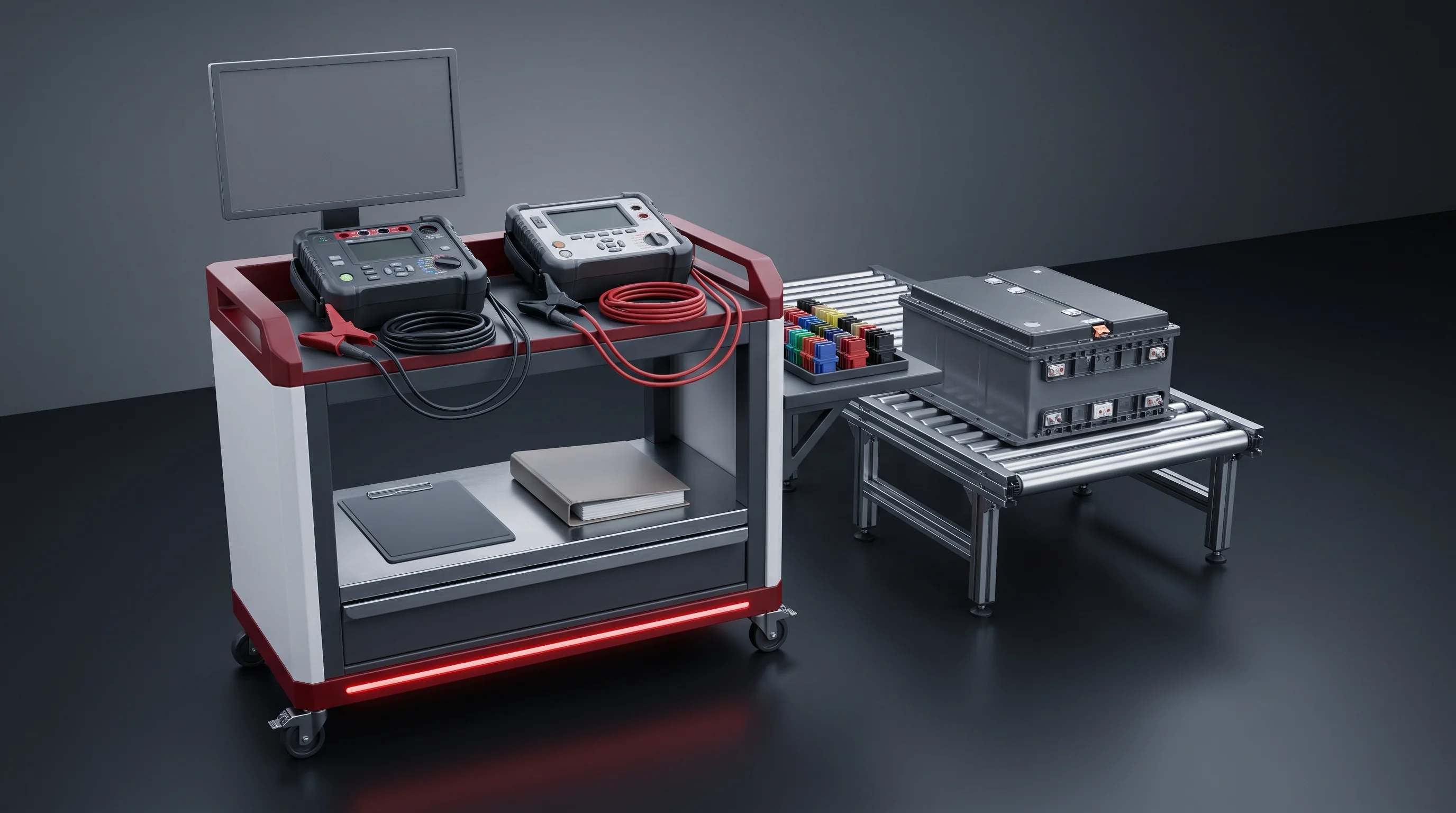
Acceptance bench where the 8 hour site run is counted at the loading point
Pre-assembly bay with a line powered up in its shipping configuration

Send and return

Battery Pack Line Factory Layout & Utilities Reply

Six things on the way out, four on the way back, within 24 hours.

Send

  1. A floor plan carrying bay length and width.
  2. The column grid and its spacing.
  3. Clear height per bay measured to the lowest obstruction, with the run it applies to.
  4. Slab notes covering trenches, pits, joints and mezzanines.
  5. Anything standing in the hall today.
  6. Your target takt or annual output.

Returns within 24 hours

  • Which of the three tiers fit your bay straight, which fit folded and which do not go in at all.
  • A layout drawn into your building with both segments and the handover placed.
  • The utility schedule for that tier against the seven rows above.
  • A list of what in the building has to move first.

If none of the three fits, that arrives in the first reply rather than after a drawing. A bay short on width and a bay short on height are different conversations, and only one of the two is usually solved by folding the line.

Spares shelf and remote diagnostics station behind the layout drawing
Behind the drawing are 26 engineers across mechanical, electrical and control, laser and vision process, and field installation, working out of a 6,000 square metre assembly hall. How the company is put together is on the about page.
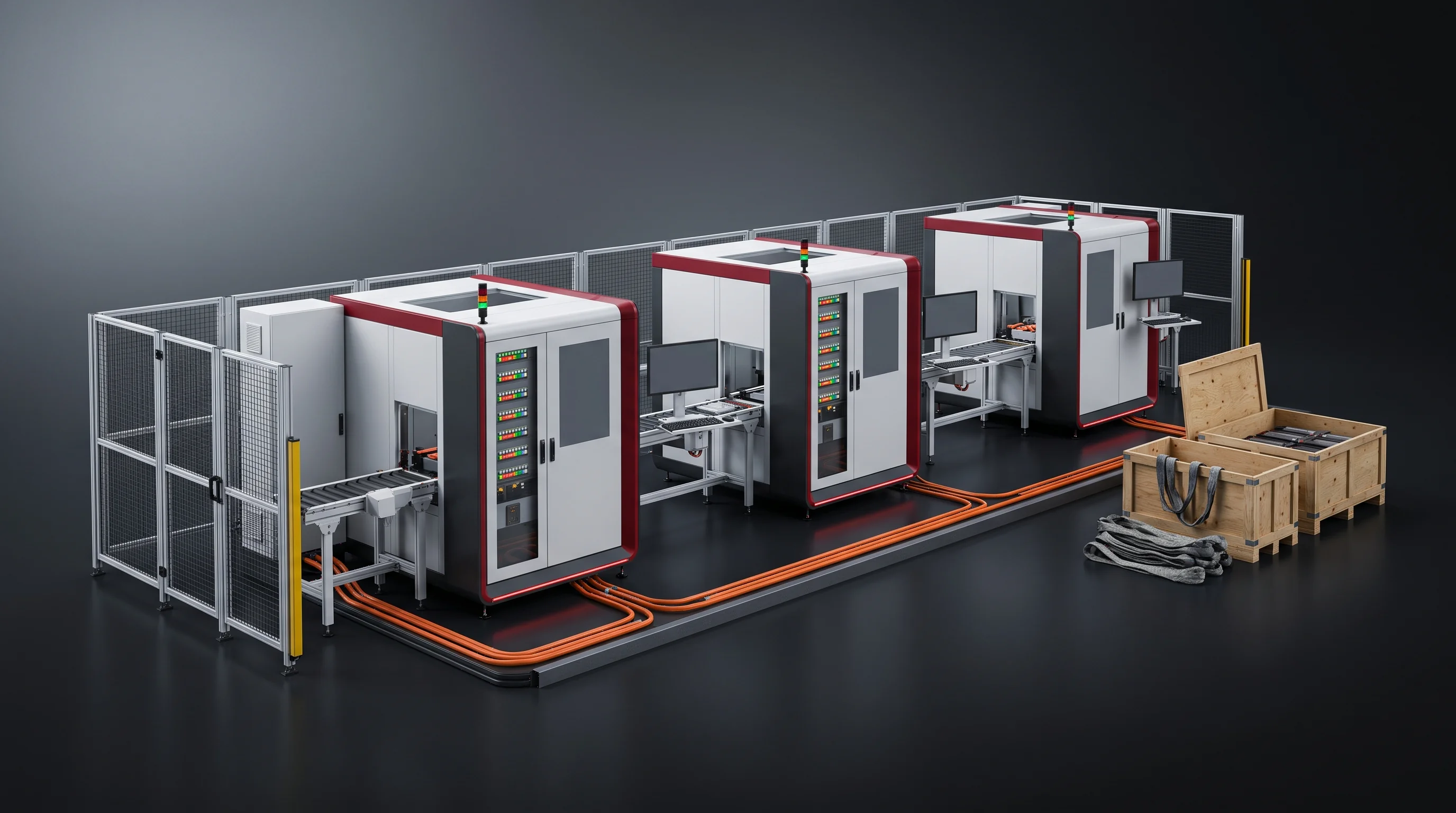
High-automation pack line drawn into a bay with both segments placed
The layout returns with both segments and the handover placed, and a list of what has to move first.

How to reach you

[email protected]

Start the layout enquiry

Battery Pack Line Factory Layout & Utilities Enquiry

More than 40 line segments have been built for plants in 12 countries, as whole lines, single stations and segment retrofits, and the same layout drawing and utility schedule come with all three. The company holds ISO 9001, CE and RoHS. Wear parts ship within 48 hours and remote diagnostics connect to the line. Send your bay dimensions and the clear height to the lowest obstruction, and the tier answer with a layout drawn into your building comes back within 24 hours. You can also start on the contact page.

Phone / WhatsApp
Address
Wuhan, Hubei, China
Response
Within 24 hours