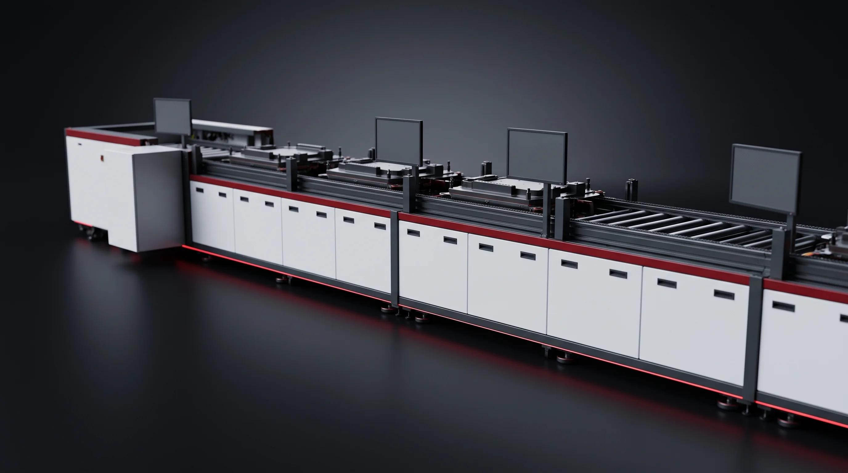
Module segment · 17 stations
Battery Module Assembly Line, Seventeen Stations
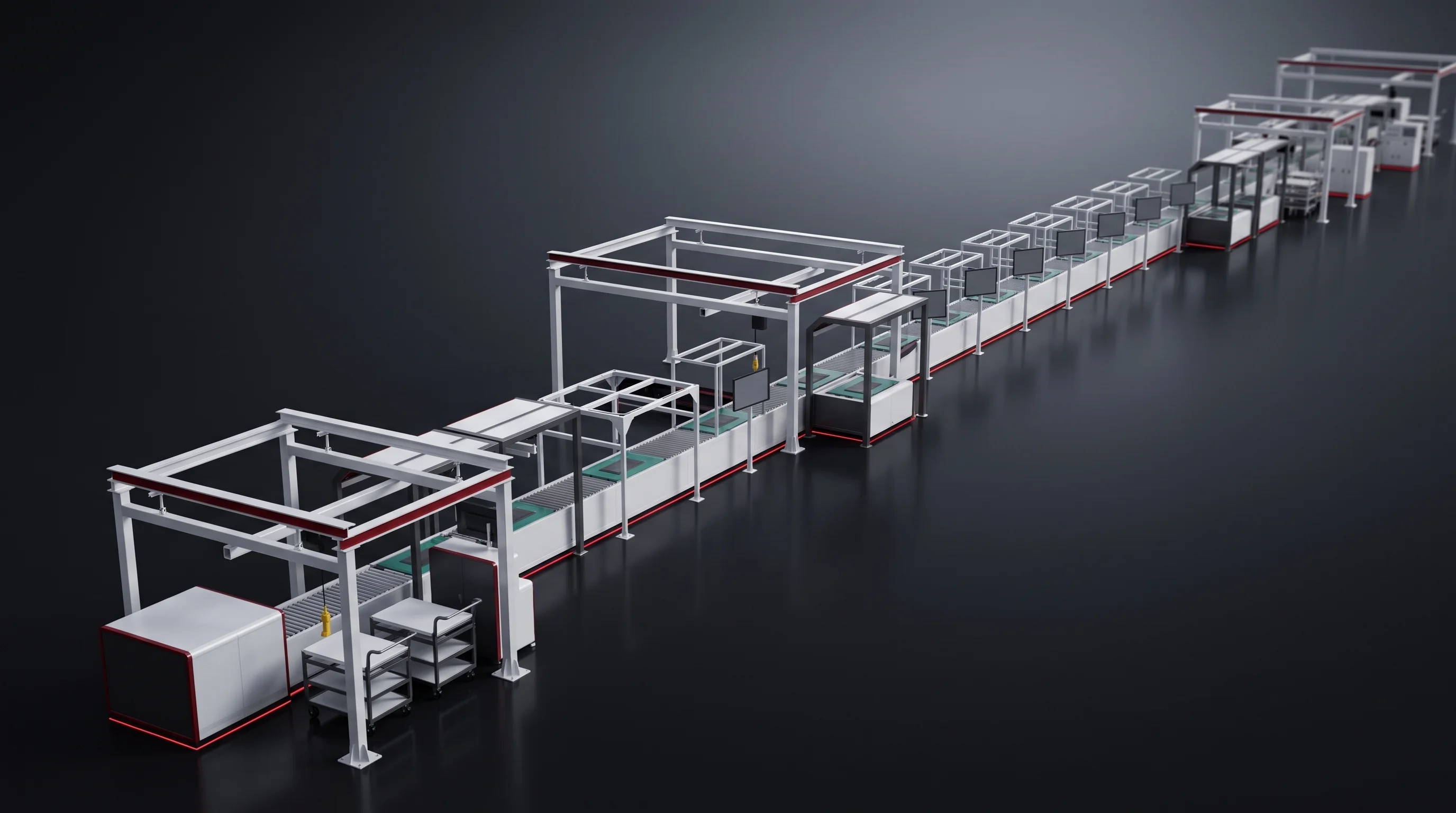
All 17 stations of the battery module assembly line, each labelled AUTO, SEMI-AUTO or MANUAL for BLP-P8S at 4 to 8 PPM and BLP-P15 at 12 to 15 PPM. Graded cells go in at station 01; welded, banded and tested modules leave station 17 on their fixtures, each carrying its press curve, weld recipe and end-of-line results. Send the cell datasheet and module drawing; the station list with a level against your tier comes back within 24 hours.
- 4 / 3operators On BLP-P8S and BLP-P15 inside the module segment. Cell handling ahead of it is staffed at 4 on both.
- ≥1000N Pull force on every weld coupon at acceptance, on your busbars, before the segment ships.
One delivered scope
Battery Module Assembly Line Scope, One Delivered Segment
Graded prismatic cells arrive on pallets at one end. Welded, banded and tested modules leave on their fixtures at the other, 17 stations later. The segment is quoted, built, powered up in the pre-assembly bay and accepted as one scope, on one of two tiers.
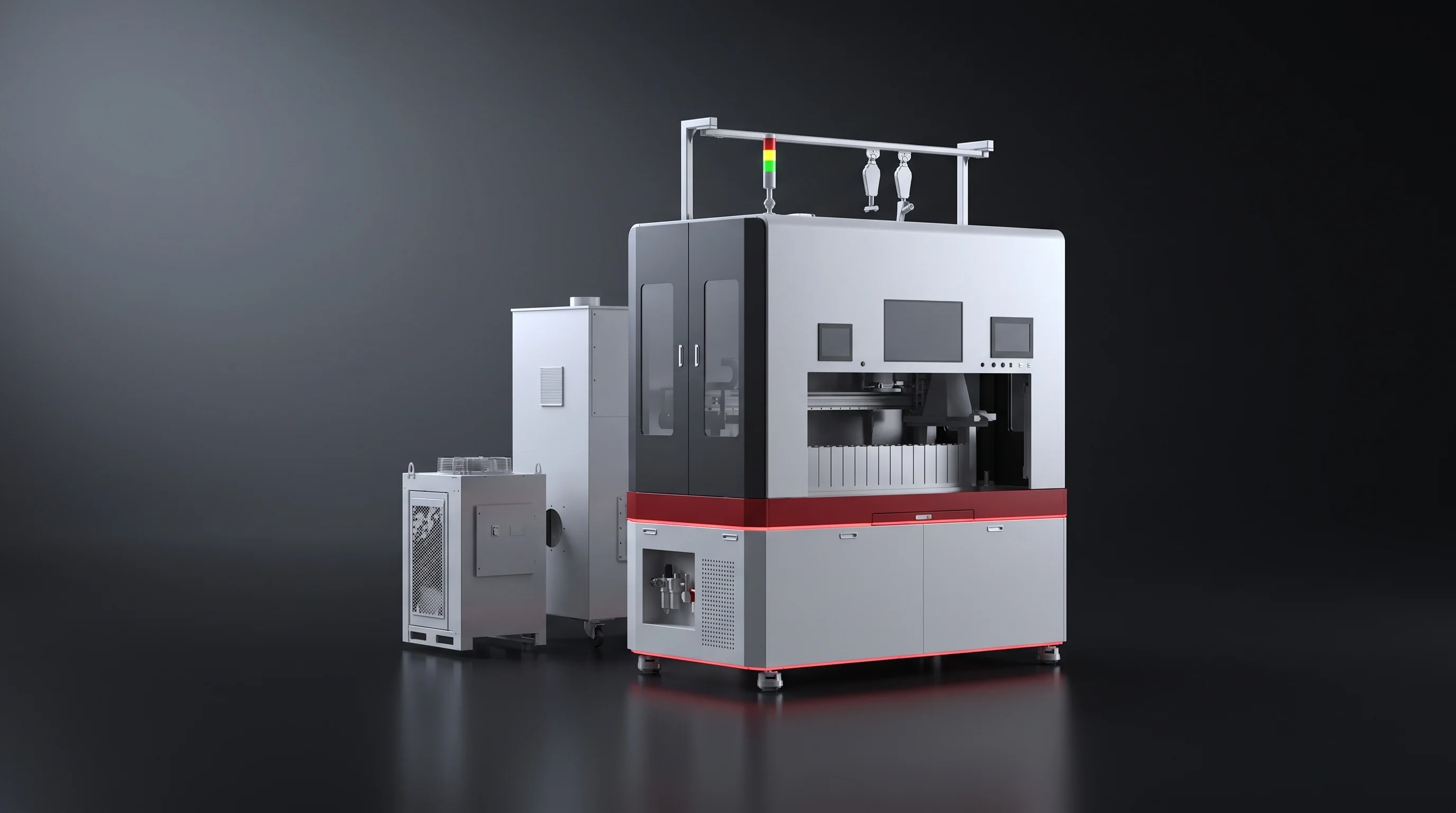
PPM counts cells entering the line at station 01, not modules or packs leaving it.
Who specifies this segment
- Commercial and industrial storage pack plants.
- Grid-scale storage integrators moving from bought-in modules to their own.
- Residential storage manufacturers adding a prismatic module line.
- EV module suppliers, on a different envelope and fixture set.
Station 01 to station 17
From Sorted Cells to Tested Modules
What arrives is a pallet of cells in foam trays. What leaves is a module that has been graded cell by cell and carries a file. Everything between is one of the 17 stations.
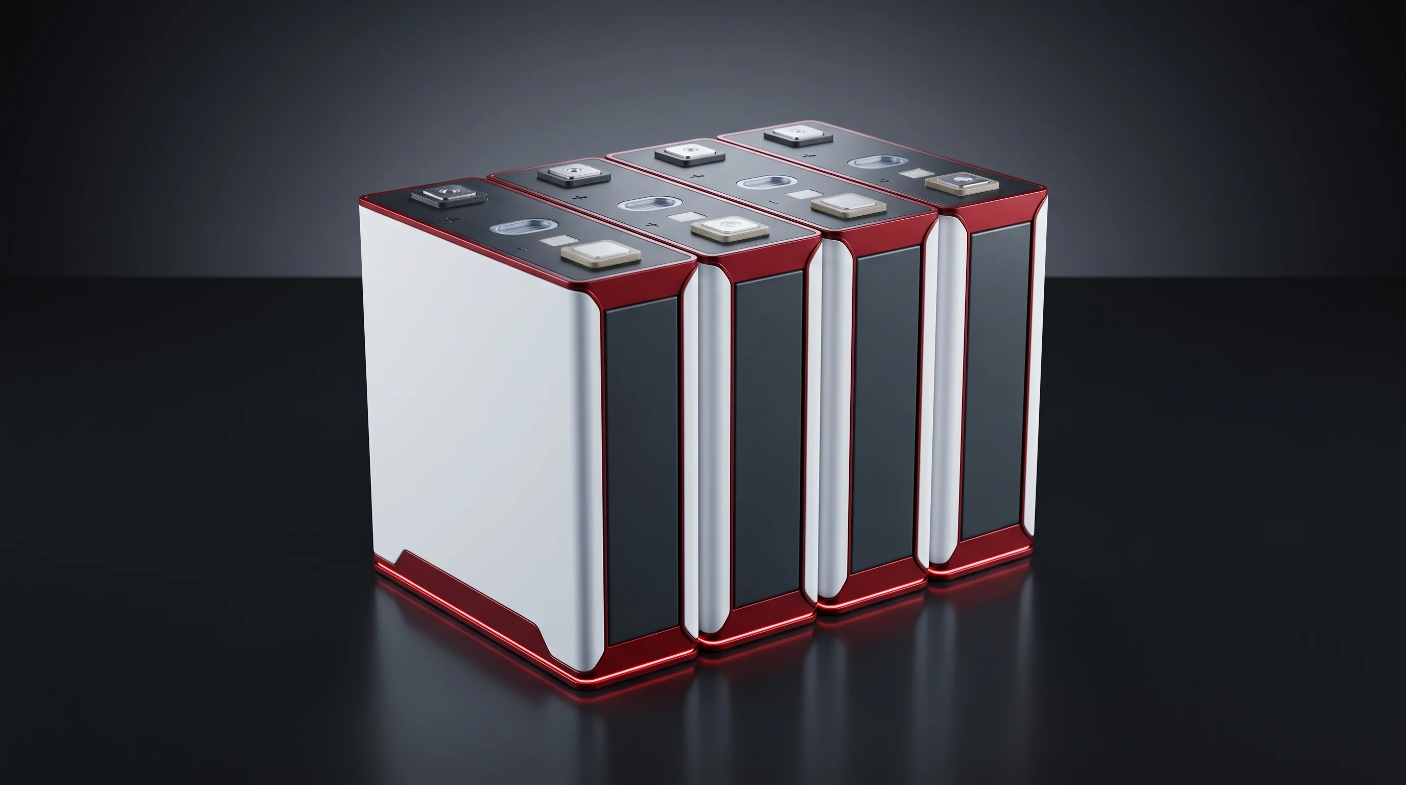
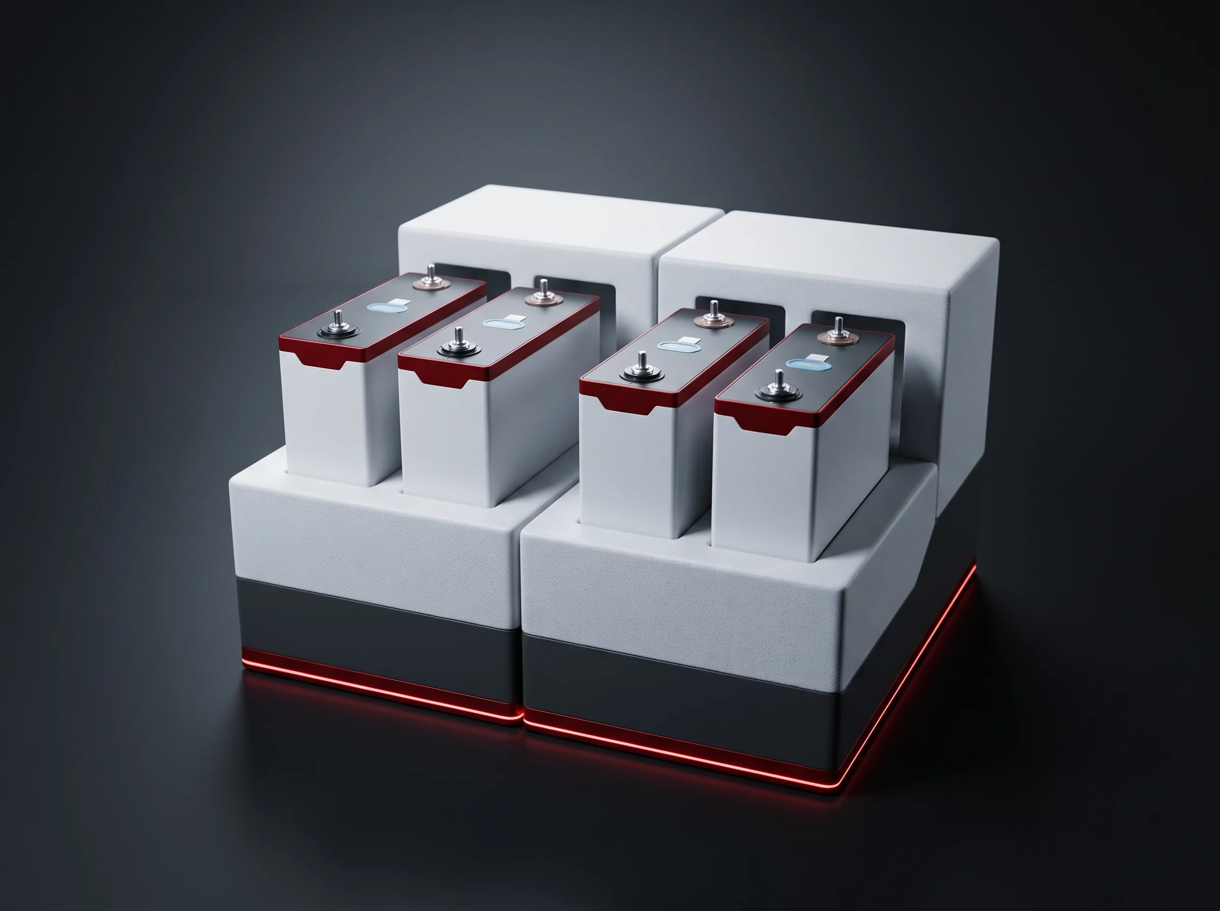
A pallet of prismatic cells in foam trays
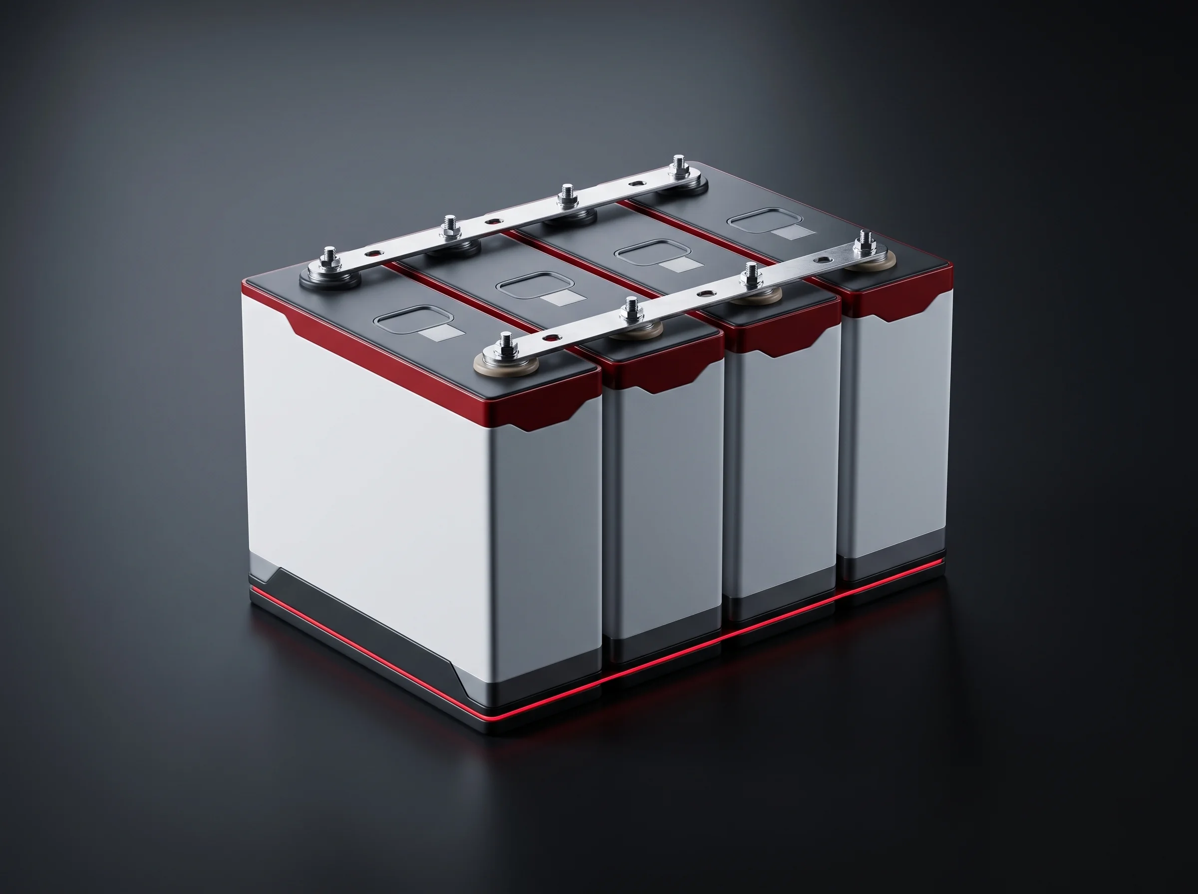
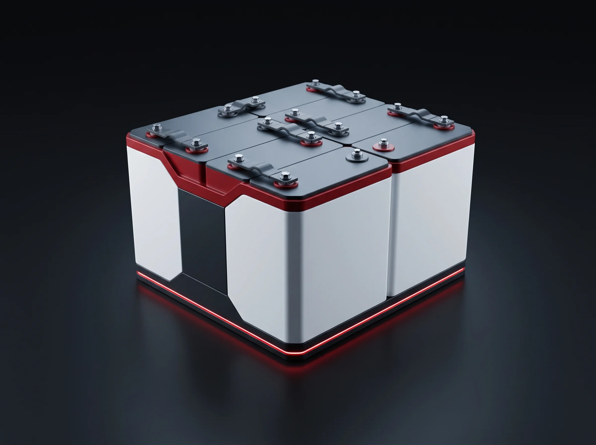
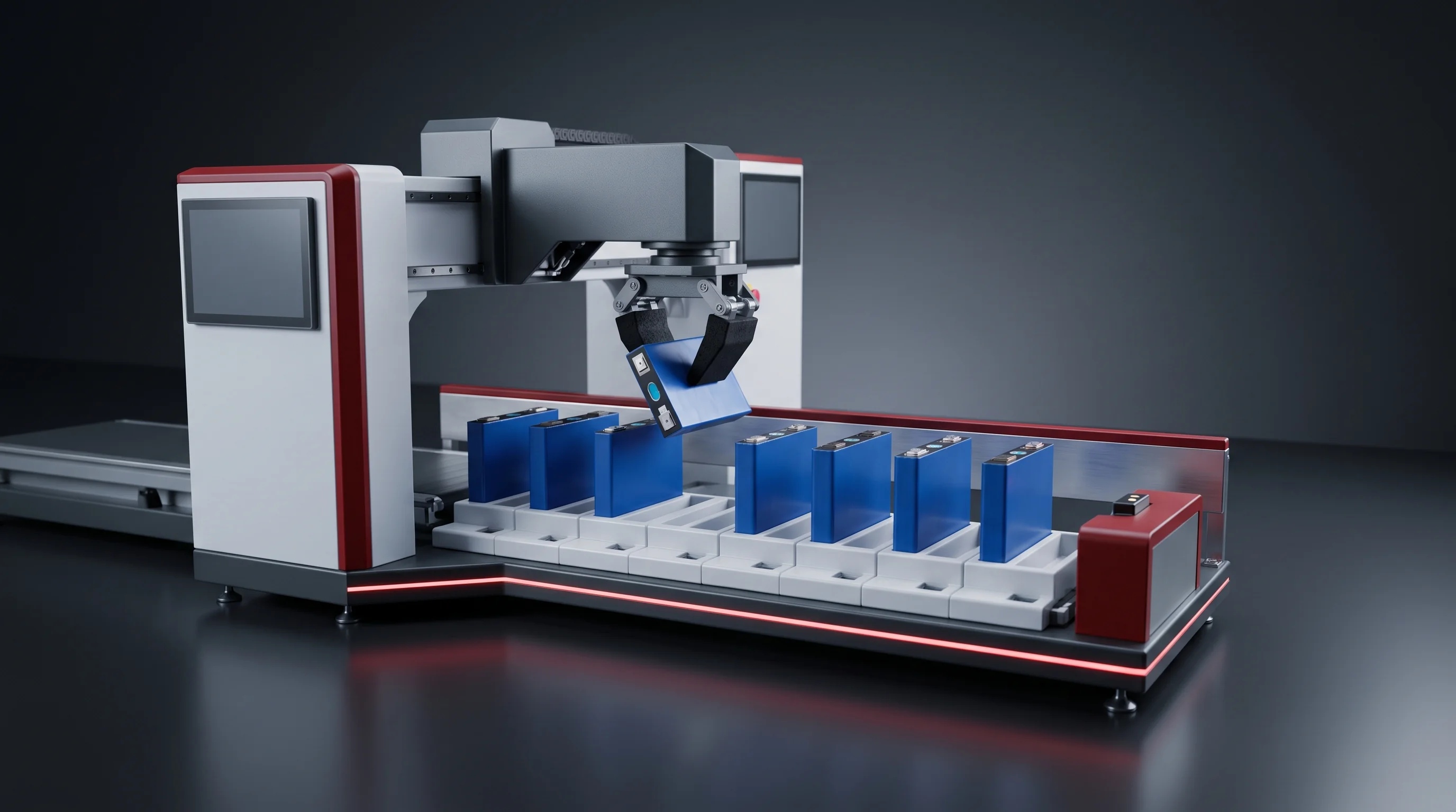
- Blueprint cell: 280 or 314 Ah prismatic at 71.3 × 174 × 207 mm, picked five at a time.
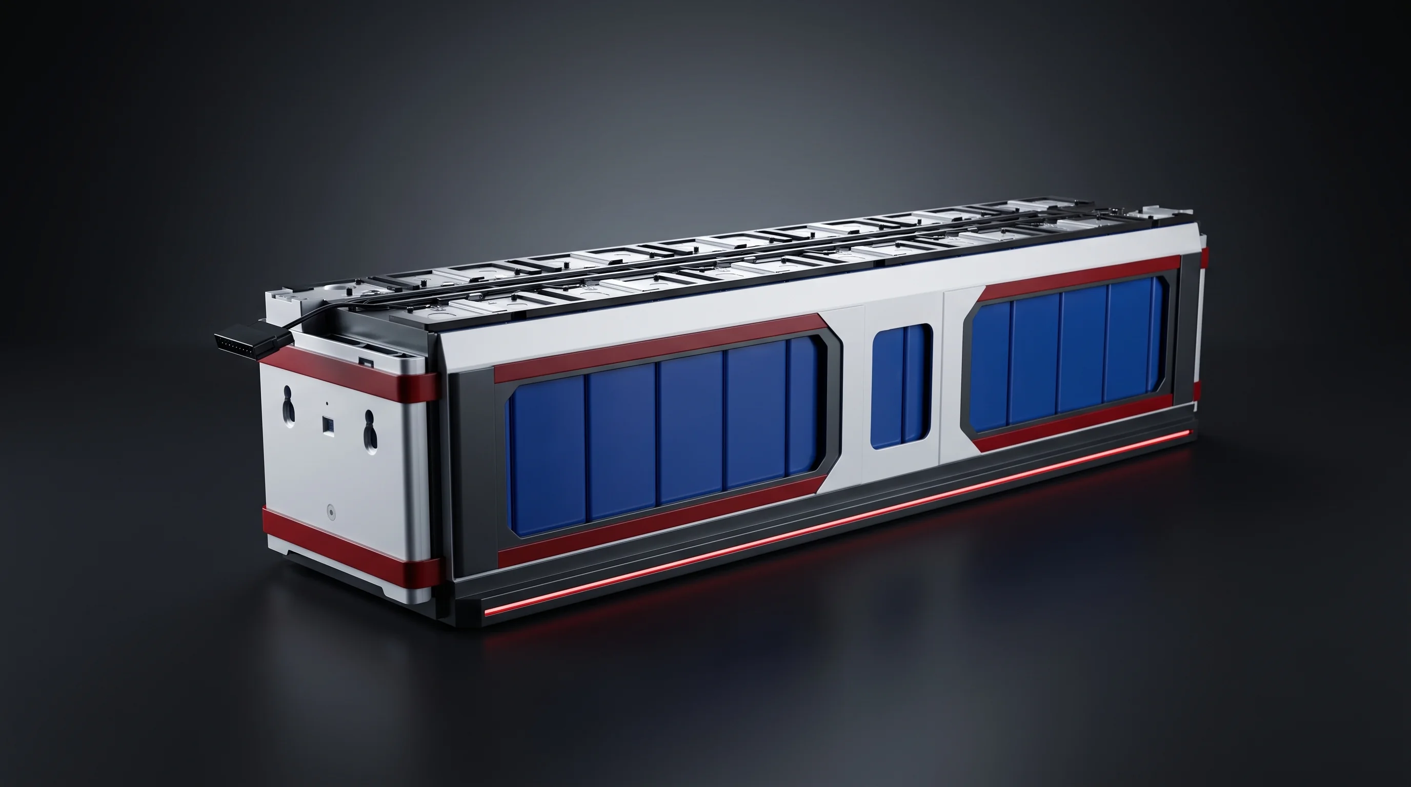
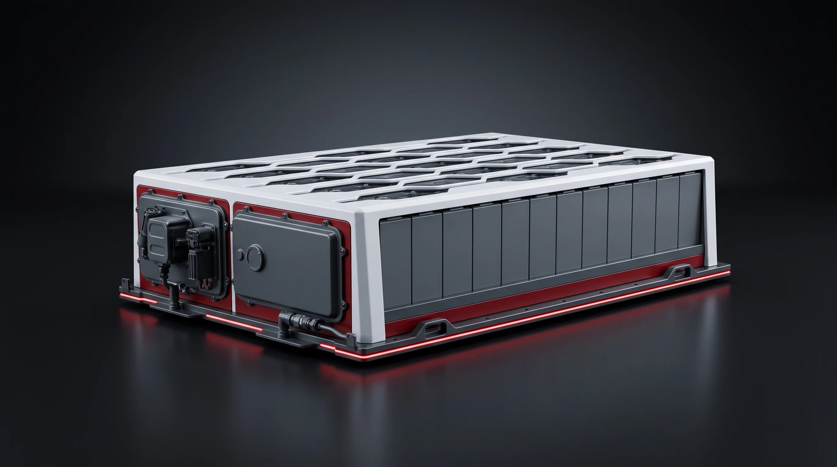
- Built into a 1P13S module of 978.4 × 178.9 × 205 mm, weighing 100 kg or less.
- Graded at station 02 on OCV and resistance; NG cells ejected, the gap refilled.
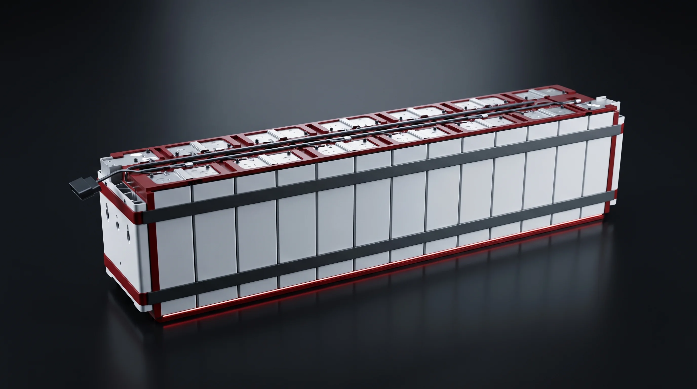
A module located on the fixture the pack segment expects
- Stacked, pressed to a known length and banded; addressed, welded, cleaned and inspected.
- Polarity and insulation tested, communication checked, end-of-line tested with a verdict filed.
- Located on the fixture the insertion station is built around, records already in your MES.
EV modules run the same 17 stations
EV module suppliers run the same sequence in the same order as storage customers. What changes is the envelope and therefore the fixtures: stacking pitch, pressing length, busbar geometry and CCS footprint come off your module drawing.
Compatibility envelope
The Cell and Module Envelope the Segment Takes
Six ranges decide whether your module runs on these 17 stations without re-planning them. The red marker on each bar is the blueprint the line is quoted against; anything inside the dark band is a fixture change, not a new line.
Six ranges, one fixture change
- Cell · scale 0–240 mm
- Cell width100–220174 mm
- Cell height100–220207 mm
- Cell thickness20–8071.3 mm
- Module · scale 0–1300 mm
- Module length400–1200978.4 mm
- Module width100–300178.9 mm
- Module height100–250205 mm
- Cells per module
- 8 to 24 on the BLP-SP frame
- Blueprint module
- 1P13S, 100 kg or less
- Blueprint pack
- 1P52S from four modules, 400 kg or less
Delivered with the segment
Four Things That Come With the Segment
Each of the four is written into a document you sign or a file you receive, not claimed for the line afterwards.
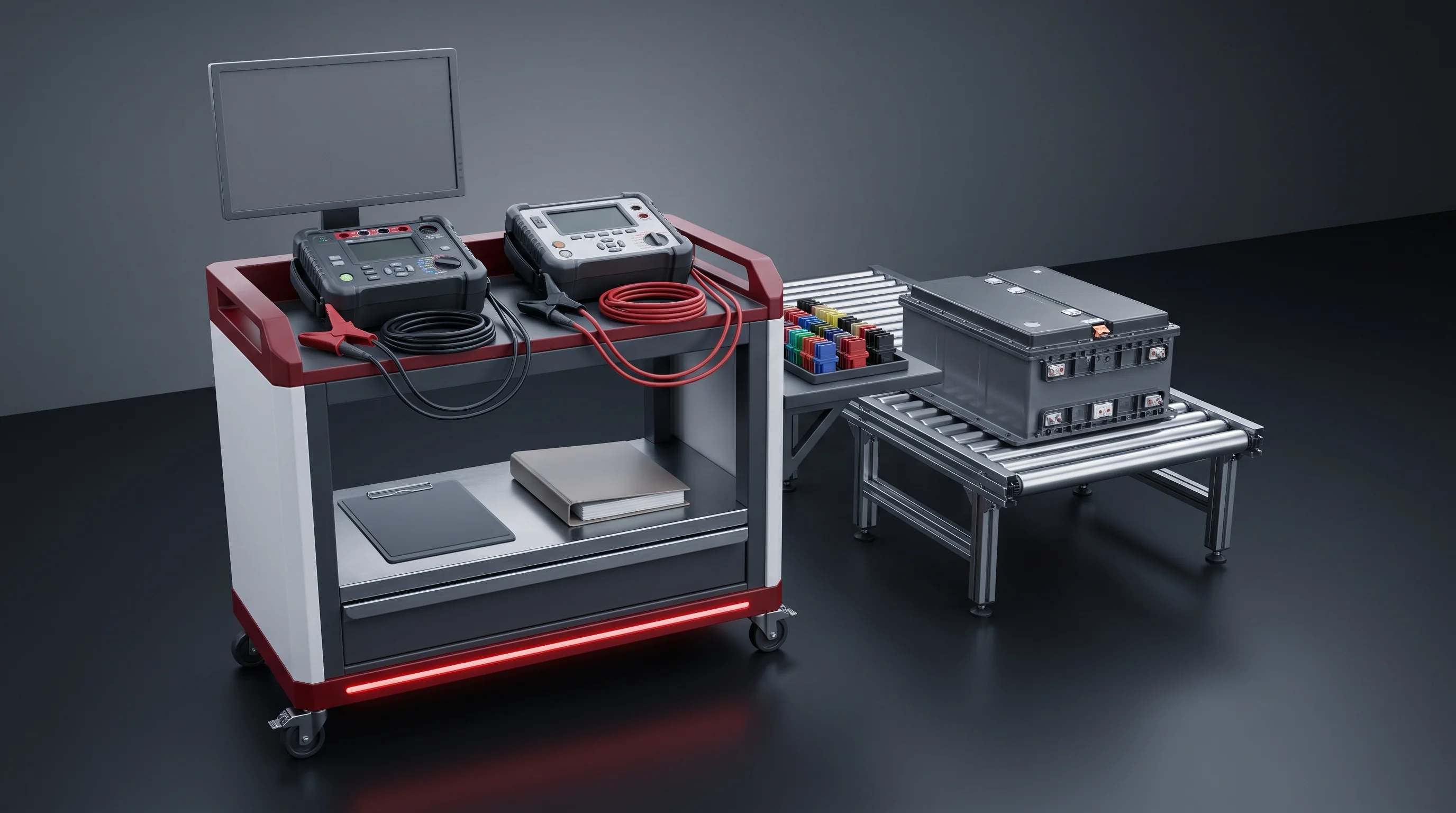
Every station labelled before you sign
- AUTO, SEMI-AUTO or MANUAL against your tier, station by station.
- In the layout package and again in the acceptance document.
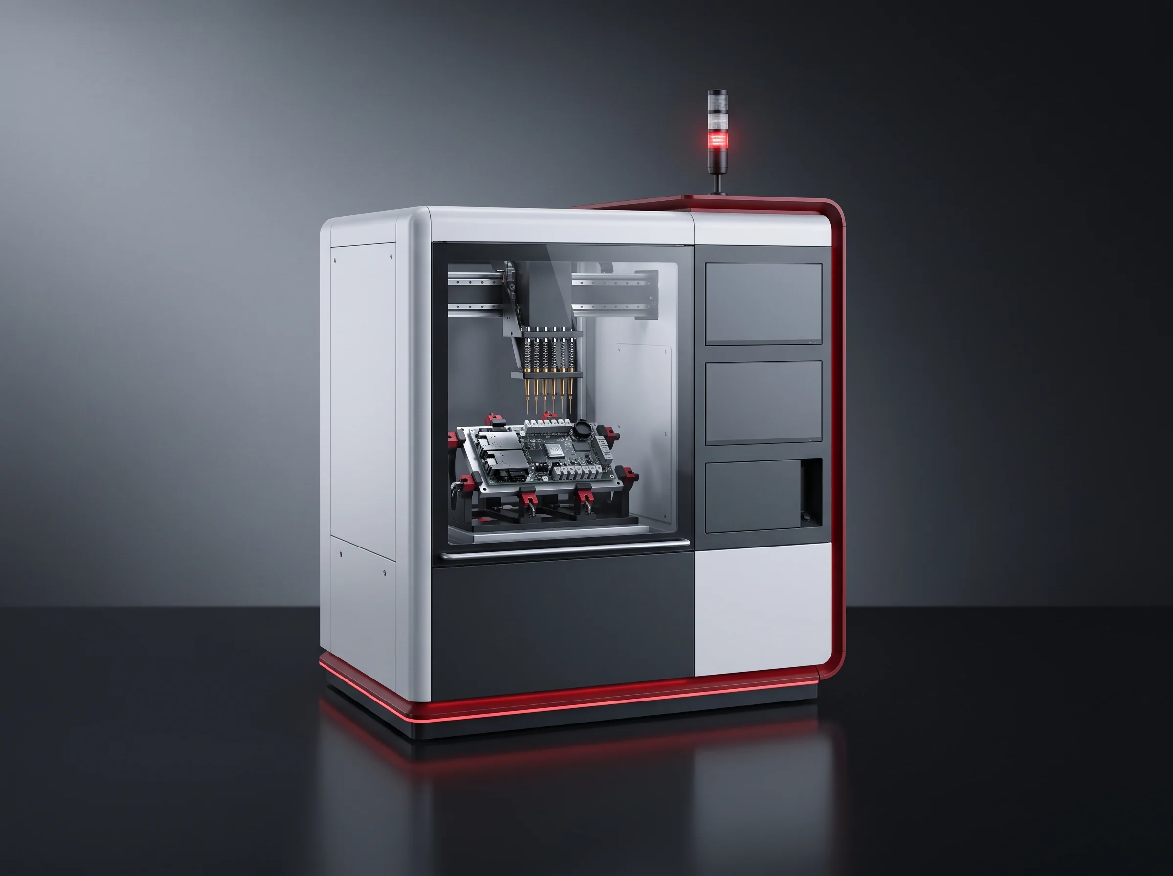
A file per module, not a pass stamp
- Press force curve, post-press length, weld recipe number and end-of-line results.
- Filed against the module number and sent to your MES over PROFINET.
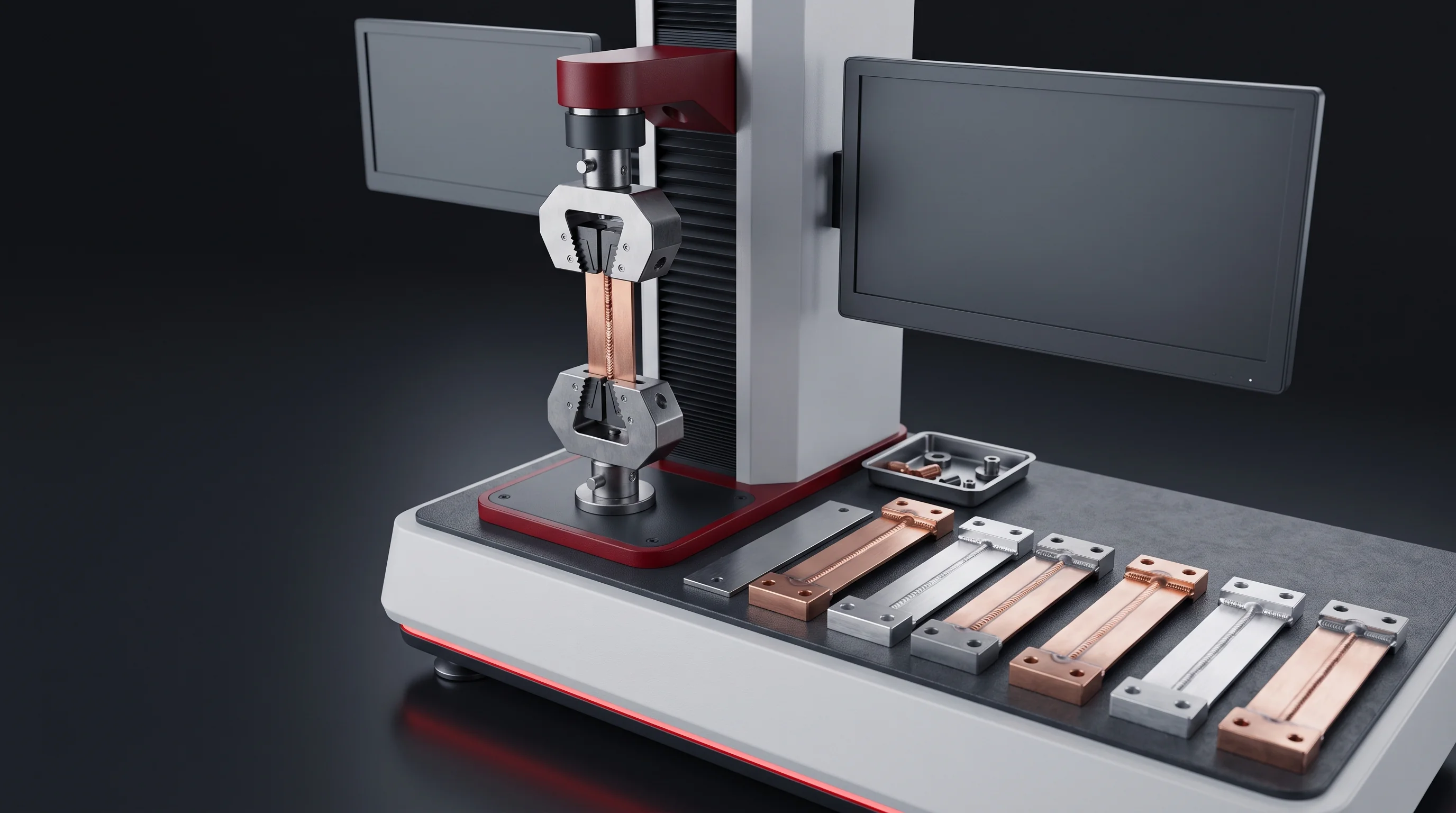
Coupons pull tested on your busbars
- 1000 N or more on every coupon during acceptance.
- Welded to the recipe stored under your busbar part number, not to a demonstration setup.
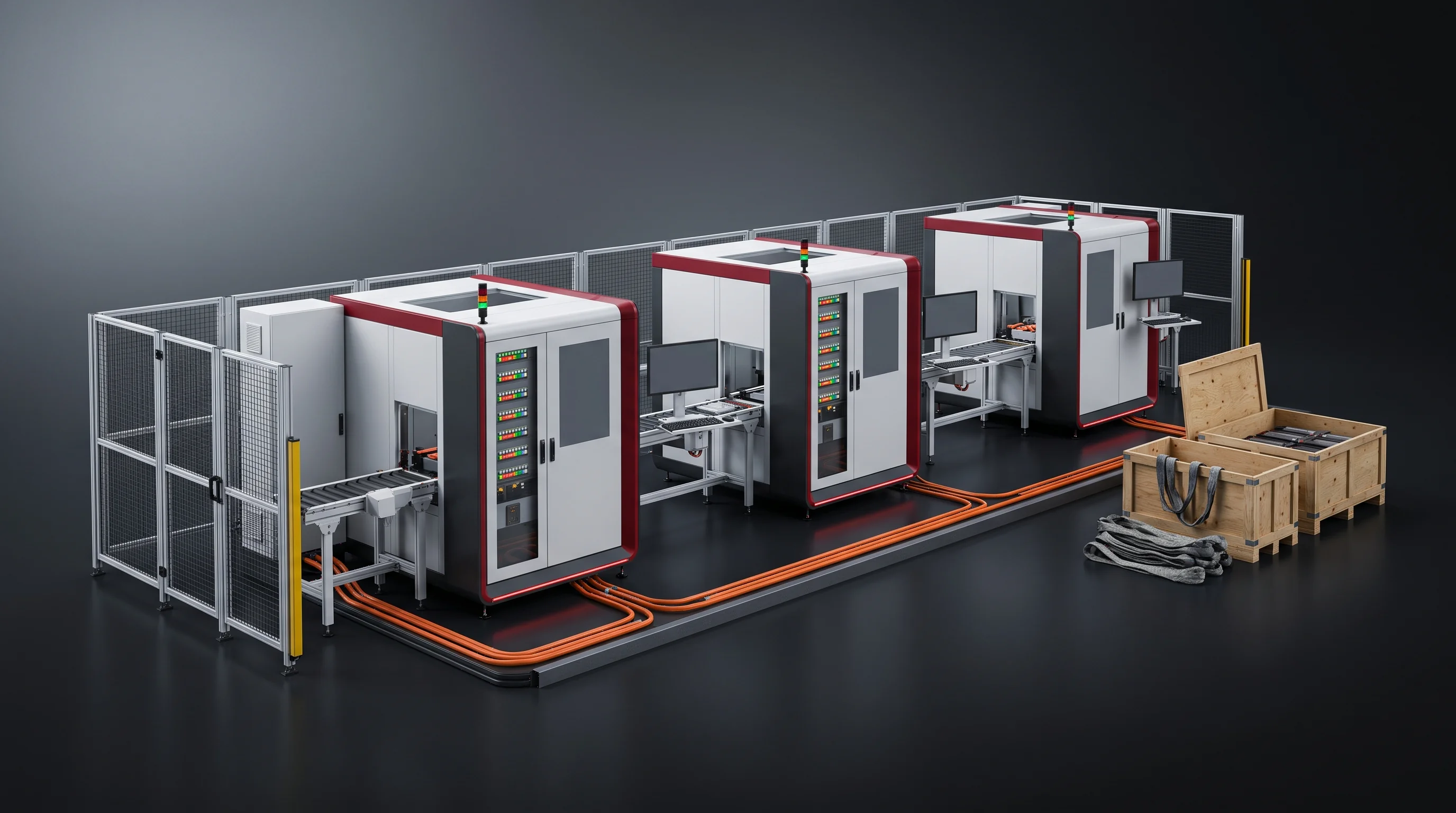
Yield signed at 99 percent or better
- Equipment-caused yield, with human factors excluded in writing.
- Measured over 8 hours continuous at target takt on your floor.
- 26engineers8 of them field installation and commissioning.
- 6,000m²Assembly hall where the segment is built up and powered before it ships.
- 3baysLine pre-assembly bays; factory acceptance runs in one of them on your parts.
The full sequence
Seventeen Stations of the Battery Module Assembly Line
The label each station carries on each tier is what goes into your layout package and your acceptance document. The headcount in the next section is built from these labels and nothing else.
| # | What the station does | BLP-P8S | BLP-P15 | Key figures |
|---|---|---|---|---|
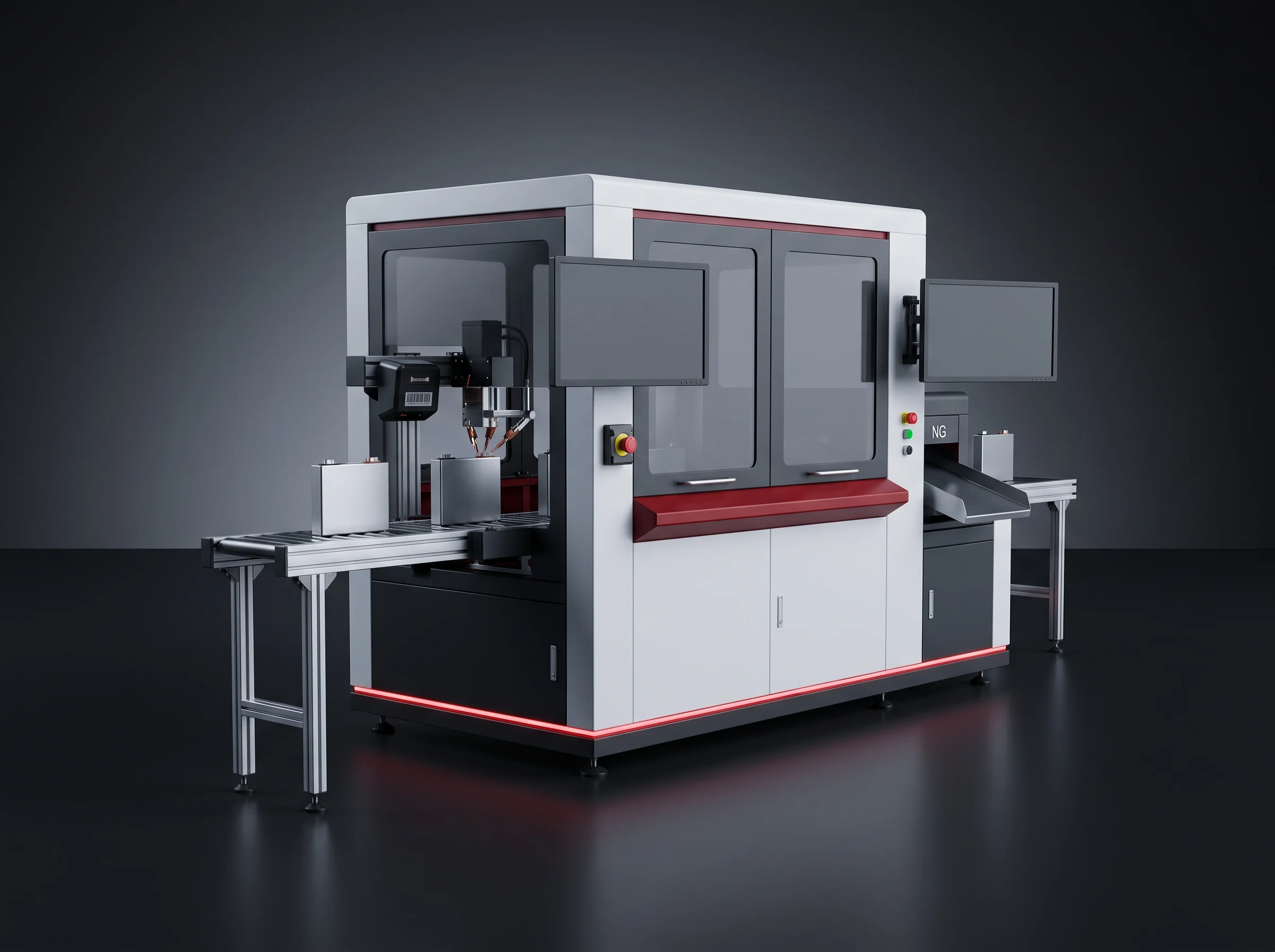
| 01 | Cell tray unloading and feeding | AUTO | AUTO | BLP-UL 220 kg payload · reach ≥2650 mm · ±0.06 mm · 5 cells per pick |
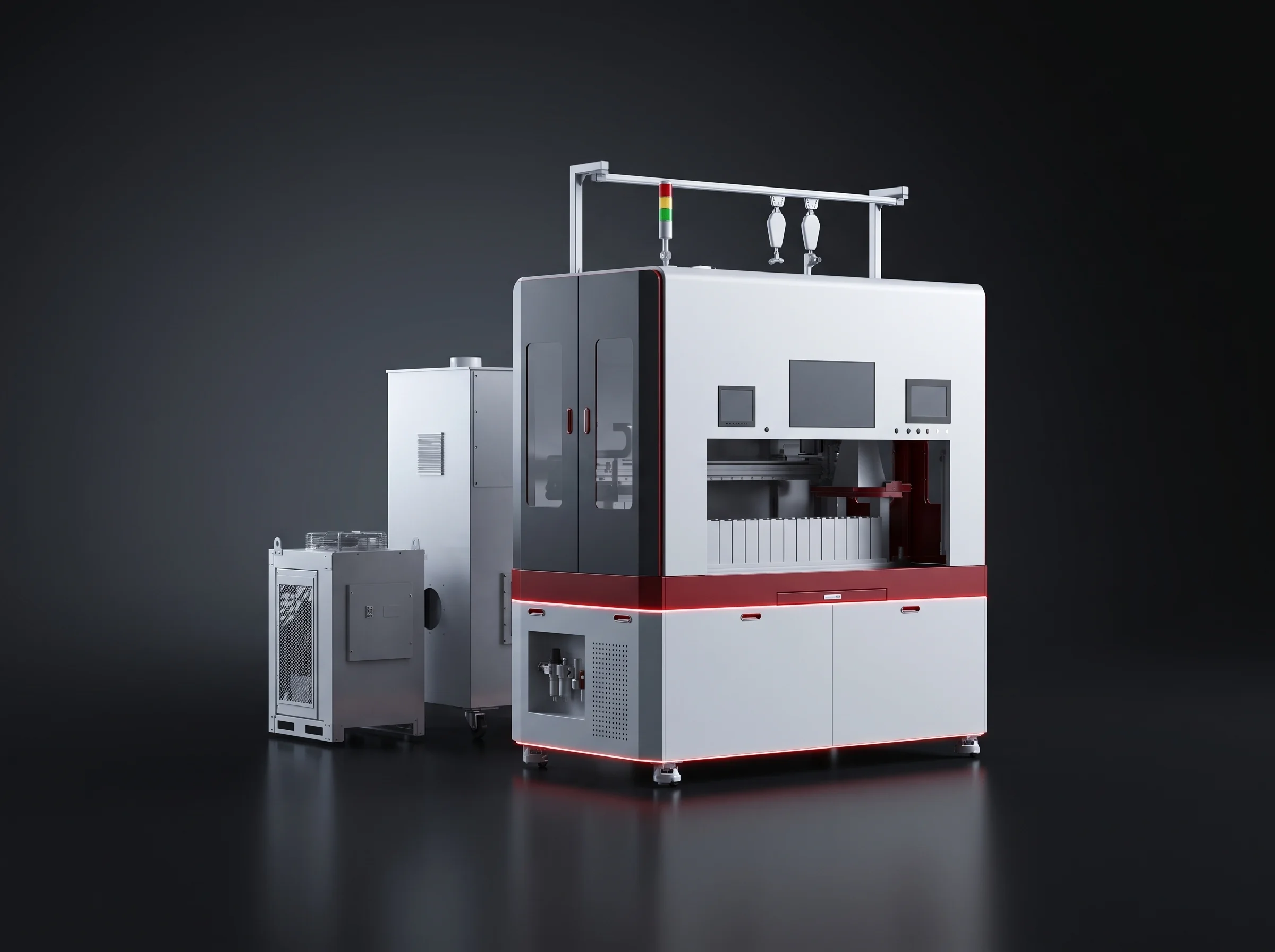
| 02 | Scanning, OCV testing and sorting | AUTO | AUTO | BLP-CS scan success ≥99.9% · voltage ±(0.01%rdg + 3dgt) · resistance ±(0.5%rdg + 10dgt) |
| 03 | NG rejection and OK refill | AUTO | AUTO | BLP-CS automatic ejection · gap refilled from the same stream |
| 04 | Cell flipping and grouping | SEMI | AUTO | — handling position built into the line |
| 05 | Large-face plasma cleaning | AUTO | AUTO | — cleaning position built into the line |
| 06 | Cell taping | SEMI | AUTO | — taping position built into the line |
| 07 | End plate and insulation sheet handling | SEMI | SEMI | — handling position, staffed on both tiers |
| 08 | Module stacking | AUTO | AUTO | BLP-SP 8 to 24 cells per module |
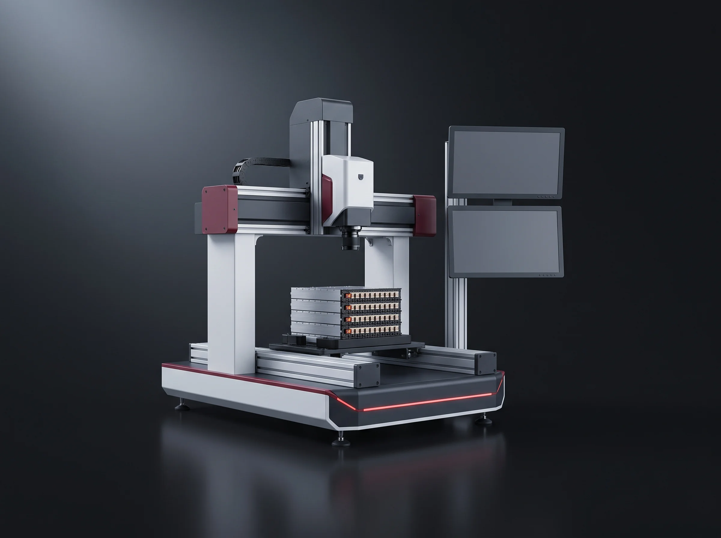
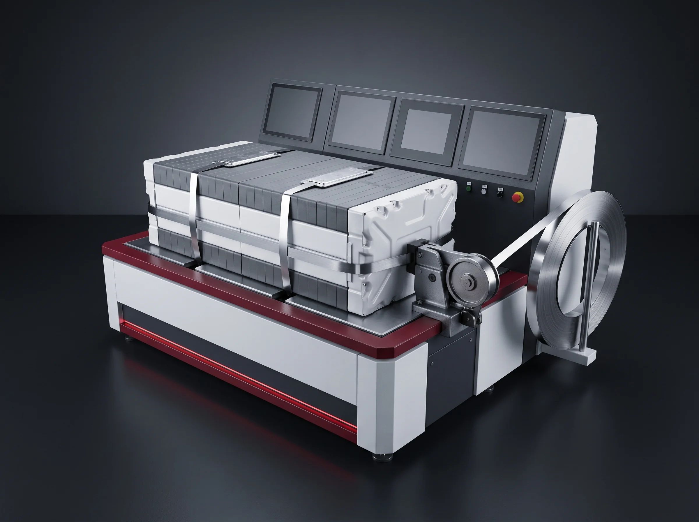
| 09 | Pressing, shaping and steel banding | SEMI | SEMI | BLP-SP 0–8000 N · 10 N resolution · 1 kHz curve · dwell 0–60 s · length ±0.1 mm measured against ±0.5 mm · cycle ≤90 s |
| 10 | Polarity and insulation testing | AUTO | AUTO | — test position on the banded module, before anything is welded |
| 11 | Terminal addressing and laser cleaning | AUTO | AUTO | BLP-AD 200–300 mm/s · ≤±0.2 mm · one vision set for location and polarity |
| 12 | Busbar plate and CCS assembly installation | MANUAL | SEMI | — fastening position; the only station that changes from MANUAL between tiers |
| 13 | Busbar laser welding | AUTO | AUTO | BLP-W6 6 kW · 50–100 mm/s · penetration ≥1.0 mm · width ≥1.5 mm · pull ≥1000 N |
| 14 | Post-weld cleaning and inspection | AUTO | AUTO | — runs at the welding station footprint |
| 15 | Manual re-inspection and communication testing | MANUAL | MANUAL | — a person looks at every module on both tiers; no tier removes it |
| 16 | Module end-of-line testing | AUTO | AUTO | BLP-EOL insulation · hipot · total voltage with internal resistance · continuity |
| 17 | Module line-off | SEMI | AUTO | — onto the fixture and the BLP-CV conveyor at 900 ±50 mm |
Seventeen stations is not seventeen machines
- NG rejection runs at the sorting station; post-weld cleaning at the welding station; stacking and pressing on one BLP-SP frame.
- They are listed separately because each is separately checkable at acceptance, not because each occupies its own floor space.
What the dash means
- Handling, cleaning, taping, fastening and inspection positions built into the line rather than separately quoted machines.
- The seven that carry their own datasheet are on the equipment page; the thresholds behind station 16 are on the EOL testing page.
Headcount
Operator Posts on Each Tier
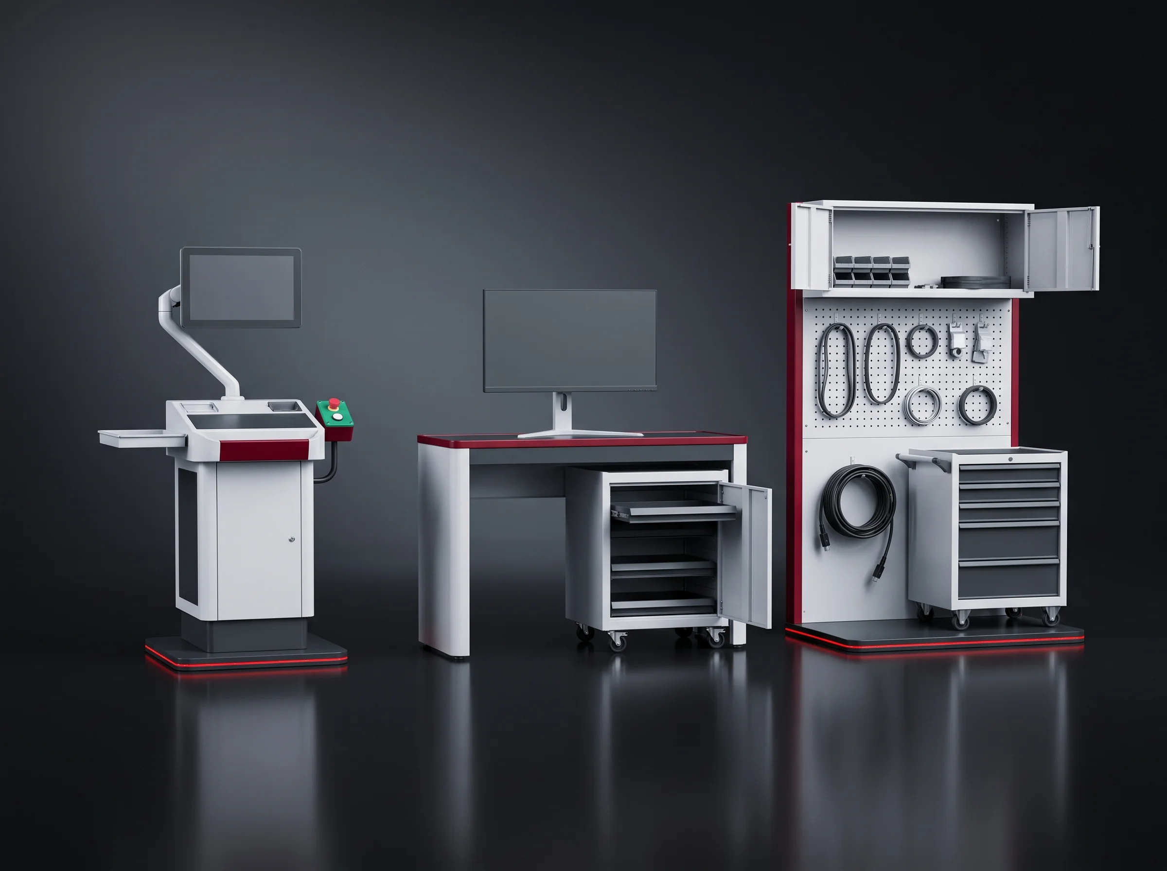
4 operators on BLP-P8S and 3 on BLP-P15 inside the segment; cell handling ahead of it is staffed at 4 on both. Use these numbers directly against your shift pattern and labour rate.
- Station 07, end plate and insulation sheet handling.
- Station 09, the banding pass on the pressing frame; also covers station 06 taping.
- Station 12, busbar plate and CCS installation; also covers station 04 flipping and grouping.
- Station 15, manual re-inspection with the communication test.
- Station 07, end plate and insulation sheet handling, unchanged.
- Station 09, the banding pass; station 12 becomes semi-automatic and folds into this post.
- Station 15, manual re-inspection with the communication test, unchanged.
- Stations 04 and 06 are automatic on this tier and need no cover.
Station 15 stays MANUAL on both tiers
A person looks at every module and runs its communication test before end-of-line testing, and no tier removes that. Every cell voltage is read back against the sorting record.
Between the two tiers
Four Stations and One Operator
The entire difference between BLP-P8S and BLP-P15 inside this segment: four stations move up one level and one operator leaves.
- 04Cell flipping and groupingSEMIAUTO
- 06Cell tapingSEMIAUTO
- 12Busbar plate and CCS installationMANUALSEMI
- 17Module line-offSEMIAUTO
Same on both tiers
- The 17-station sequence and the order it runs in.
- The fixtures, the recipes and the records written per module.
- The acceptance criteria, signed station by station before shipping.
Station 09
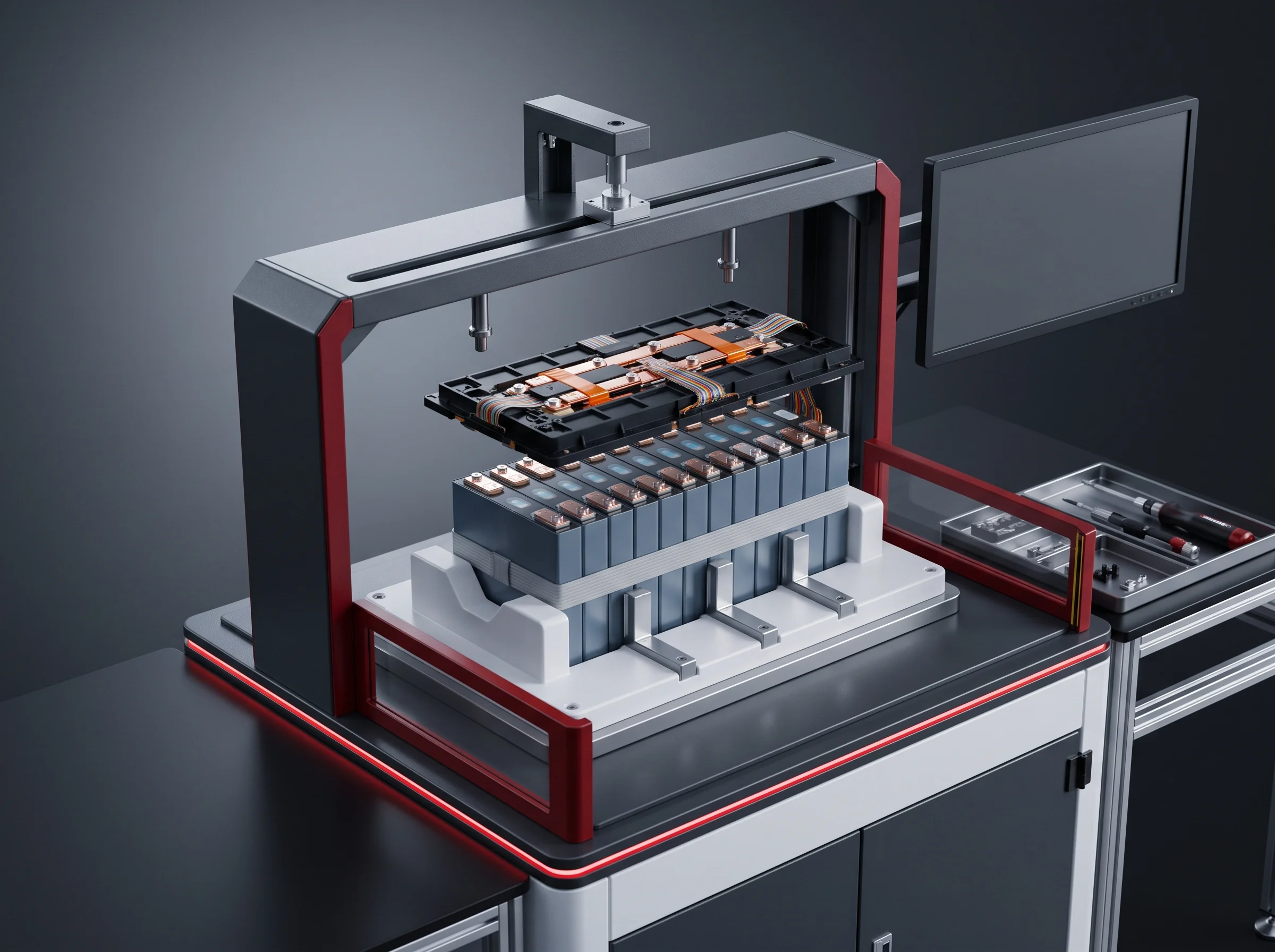
Station 09, Pressing and Banding
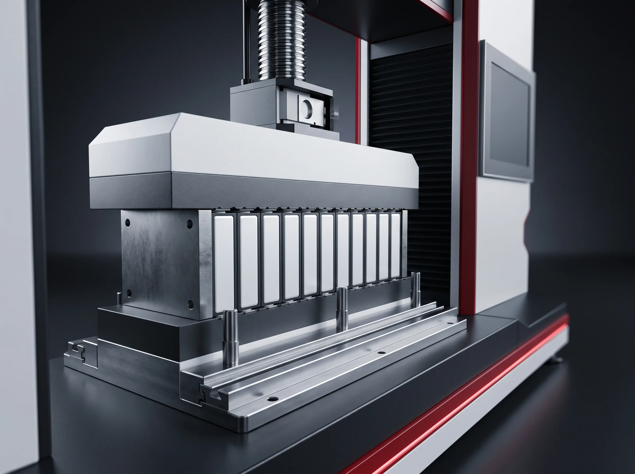
Everything from station 10 onward assumes the stack has stopped moving and is the length the pack enclosure was drawn for. Station 09 is where that becomes true.
- 0–8000NServo press force
- 10NForce resolution
- 1kHzCurve sampling
- 0–60sDwell, per recipe
- ±0.1mmLength measurement
- ±0.5mmDelivered length tolerance
- ≤90sCycle, banding included
What the press does to the stack
The stack arrives from station 08 with end plates and insulation sheets placed, 8 to 24 cells depending on your module. A servo press closes it to the recipe force in 10 N steps. Force, platen position and time are sampled at 1 kHz through approach, ramp and dwell and written as one curve.
The module is measured under load and again after release with the steel bands on, and the released length is the one that counts. A complete cycle, banding included, runs in 90 seconds or less on the blueprint 1P13S.
Who does what at this station
- The recipe holds target force, dwell, target length and banding passes, stored by module type.
- Operators select it. Only the process engineer who wrote it edits it, and quality countersigns the change.
- A module whose curve or released length falls outside its recipe is held under its module number for the process engineer. The welder never inherits it.
What leaves this station with the module
A force curve and a released length per module, and at acceptance the length distribution across a batch of your own modules pressed in front of you. Full datasheet on the module stacking and pressing station page.
Station 13
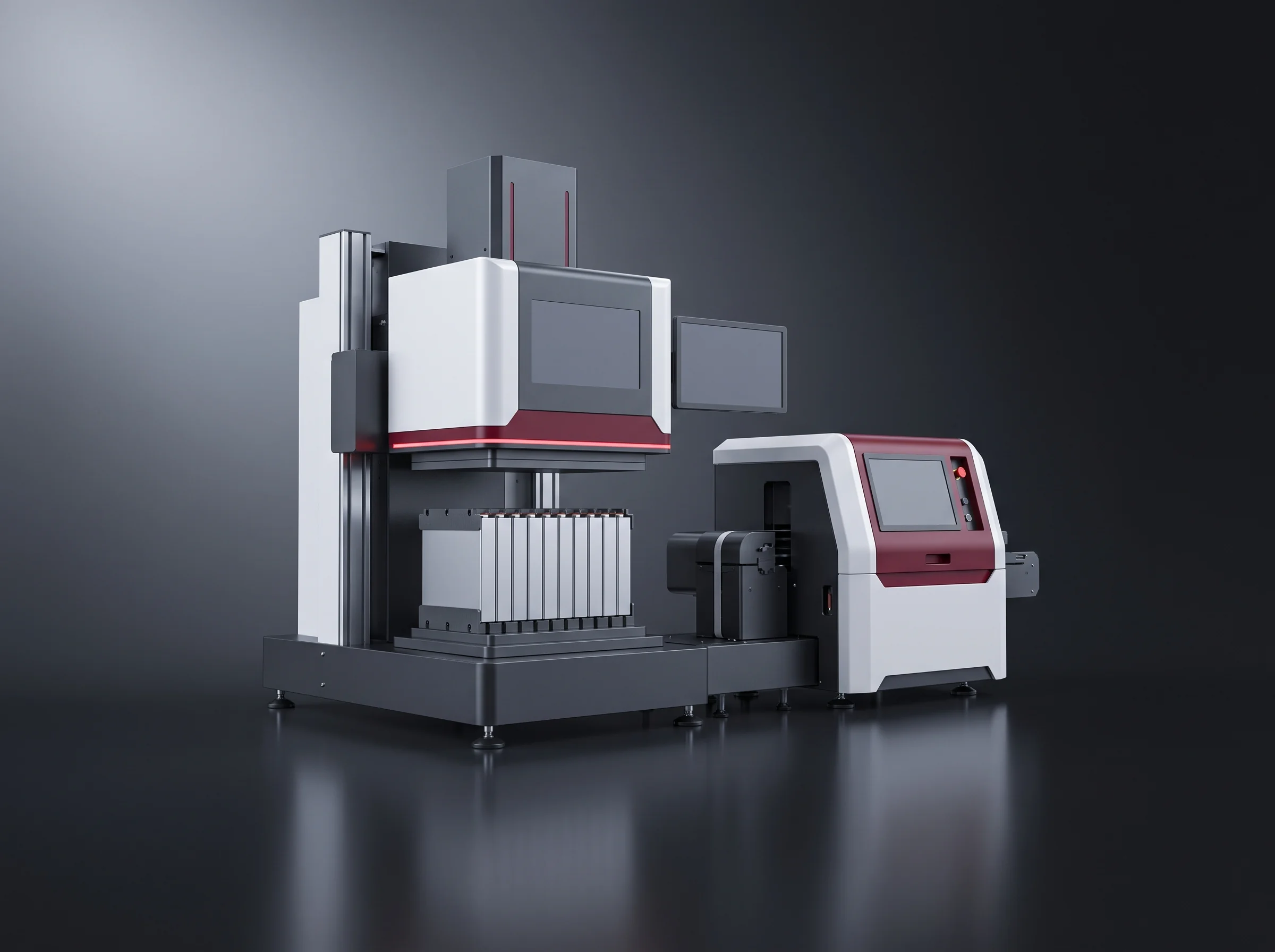
Station 13, Busbar Welding Recipes
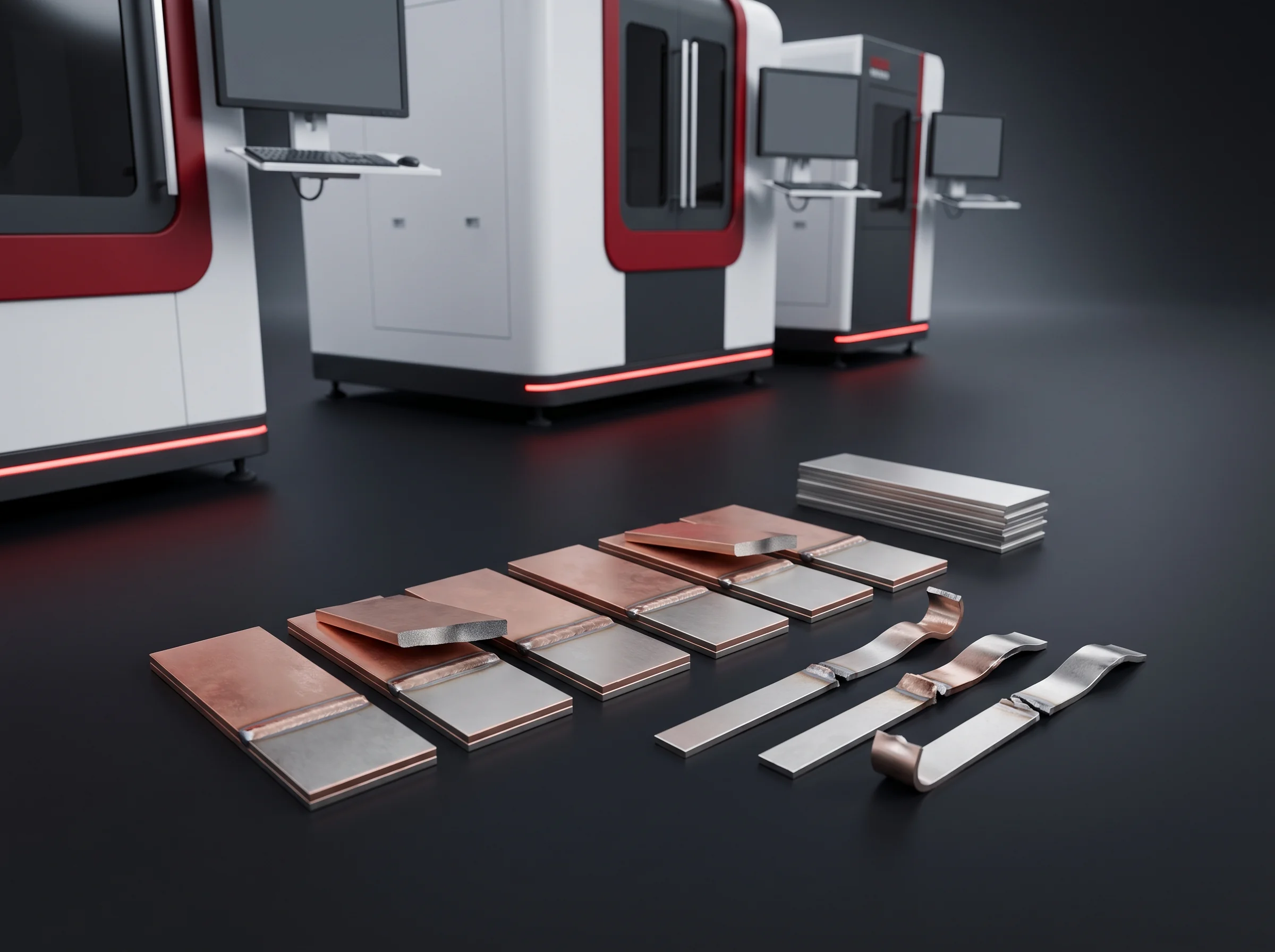
Station 13 is where the module stops being reversible. Up to it, a stack can be re-pressed and an insulation sheet replaced. After it, correcting anything underneath the joint means cutting.
- 6kWLaser source
- 50–100mm/sWeld speed
- ≥1.0mmPenetration
- ≥1.5mmWeld width
- ≥1000NPull force
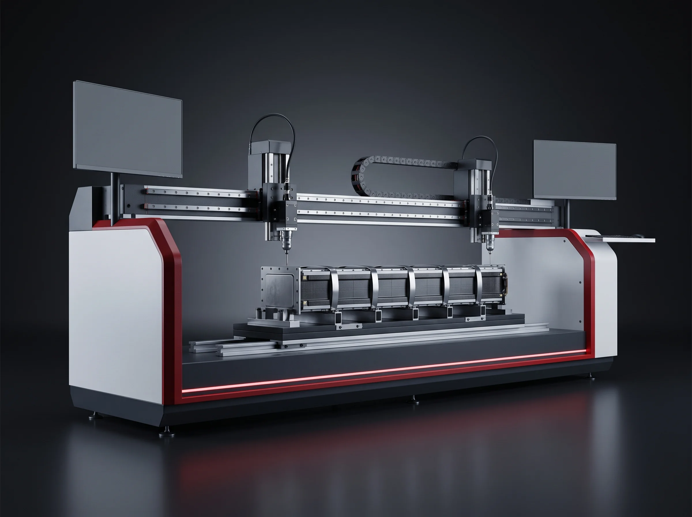
The BLP-W6 welds where it is pointed: station 11 has located each terminal to ±0.2 mm or better and read its polarity, station 12 has seated the busbar plate flat, and station 09 has fixed the length all three work from. Single-row and double-row modules run without a mechanical change.
What you receive from this station
- A recipe list covering every welded part number on your line.
- A change record per recipe: what changed, which account changed it and when.
- Both handed over at acceptance and kept being written afterwards, so a joint welded in month 18 traces to its parameter set and approver.
Station figures are on the busbar welding station page and the offline welder on the gantry laser welding machine page.
The recipe rule, the same at every station that puts energy into a part
- Recipes are stored by part number, which for welding means the busbar geometry. Operators select but never edit.
- A recipe for a new geometry is not tuned at the line. It is created offline on the BLP-WG gantry welder and run onto sample parts.
- The samples are pull tested. Once they meet 1000 N, the recipe moves to the inline BLP-W6 unchanged, under the same part number and the same two signatures.
- Rework goes back to the gantry and is rewelded to the recipe stored against its own part number, never to a fresh setup.
The file that travels
Battery Module Assembly Line Records, Written per Module
A module leaving this segment carries a file rather than a pass stamp. Four record sets are written against its module number as it moves, and one sign-off is added by hand.
From station 09 BLP-SP
- The 1 kHz force curve through approach, ramp and dwell.
- The released length and the recipe number it was pressed to.
- The number of banding passes applied.
From station 10
- Polarity result on the banded module.
- Insulation result before anything is welded to it.
From station 13 BLP-W6
- The part number and recipe number each joint was welded under.
- The account that approved it and when it last changed.
From station 16 BLP-EOL
- Insulation, hipot, total voltage with internal resistance, continuity.
- Station 15 adds the re-inspection and communication test sign-off.
Records, not screens
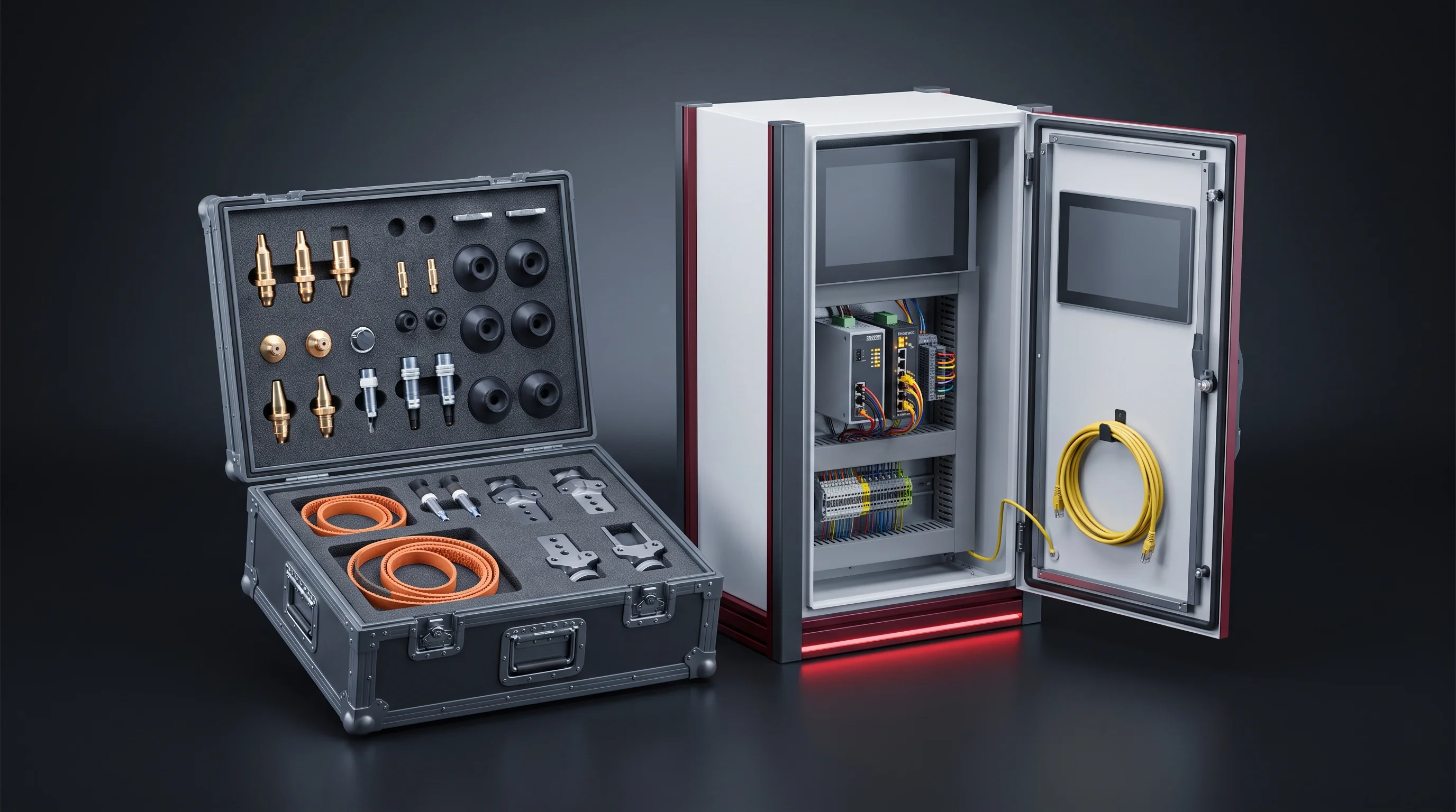
A live display tells your operator what is happening now. A stored curve tells your process engineer what happened to the module that came back from a site two years later, against the modules built either side of it on the same shift.
Your station list
The 17 Stations, Marked for Your Tier, Within 24 Hours
A cell datasheet and a module drawing resolve into a station list with a level against each station, the tooling that comes off your drawing and a layout drawn into your building.
Send the cell datasheet and module drawingStation 17 onward
The Handover to the Pack Segment
A module reaching station 17 is banded inside ±0.5 mm, welded, cleaned and inspected, polarity and insulation tested, communication checked, carrying an end-of-line verdict, and located on its fixture.
It moves on BLP-CV
The conveyor carries modules on their fixtures with stop-and-lift positioning and panels on both sides for dust and guarding. The blueprint module is 100 kg or less, so with its fixture the rating carries roughly a factor of two in hand.
- ≥200kgLoad on the fixture
- ≤20m/minConveying speed
- 900±50 mmTransfer height, adjustable
Send the height and pitch of your pack-side conveyor
With the module fixture drawing, the interface comes back marked up: what matches, what we adjust, what you adjust. PROFINET carries the module records across at the same point, so the pack segment’s MES entry starts with the file already written.
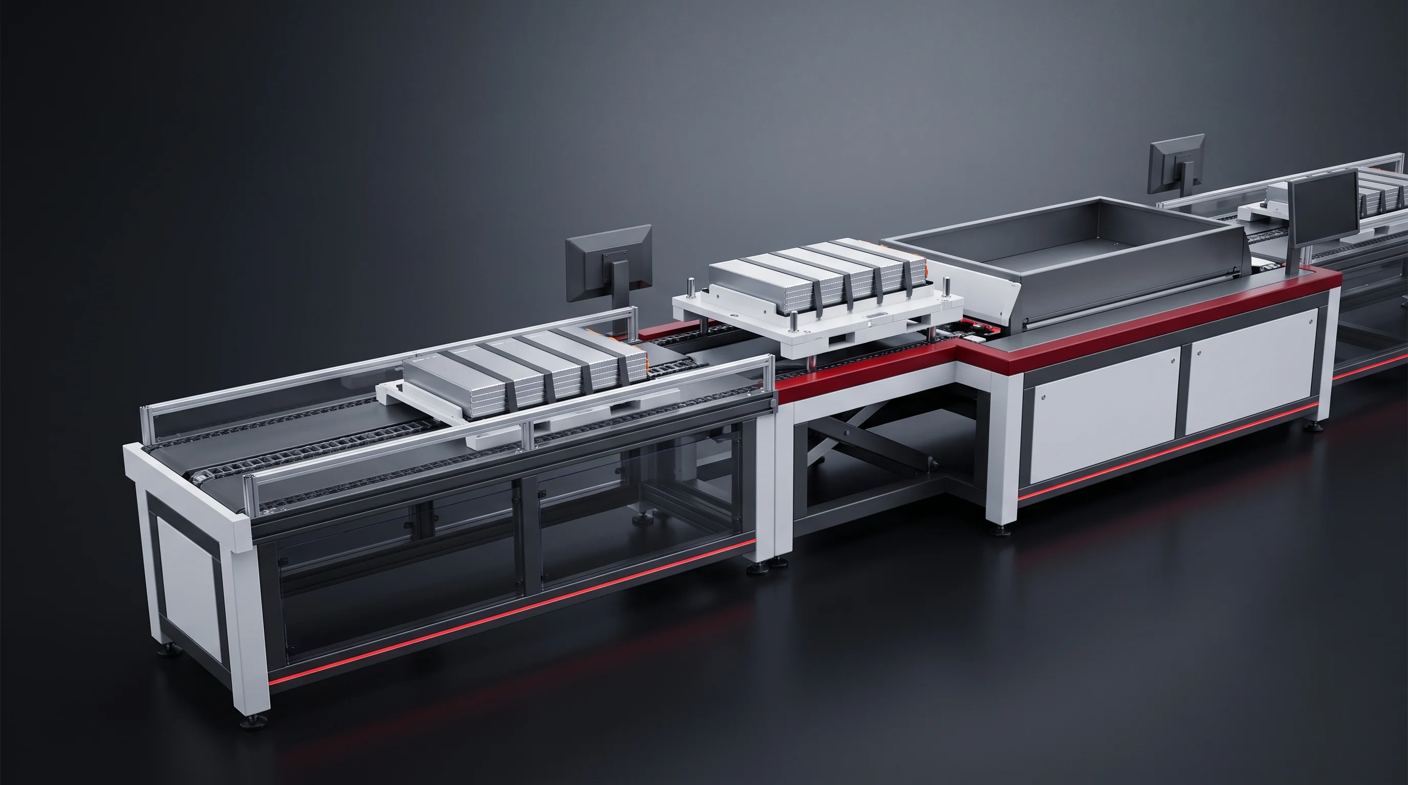
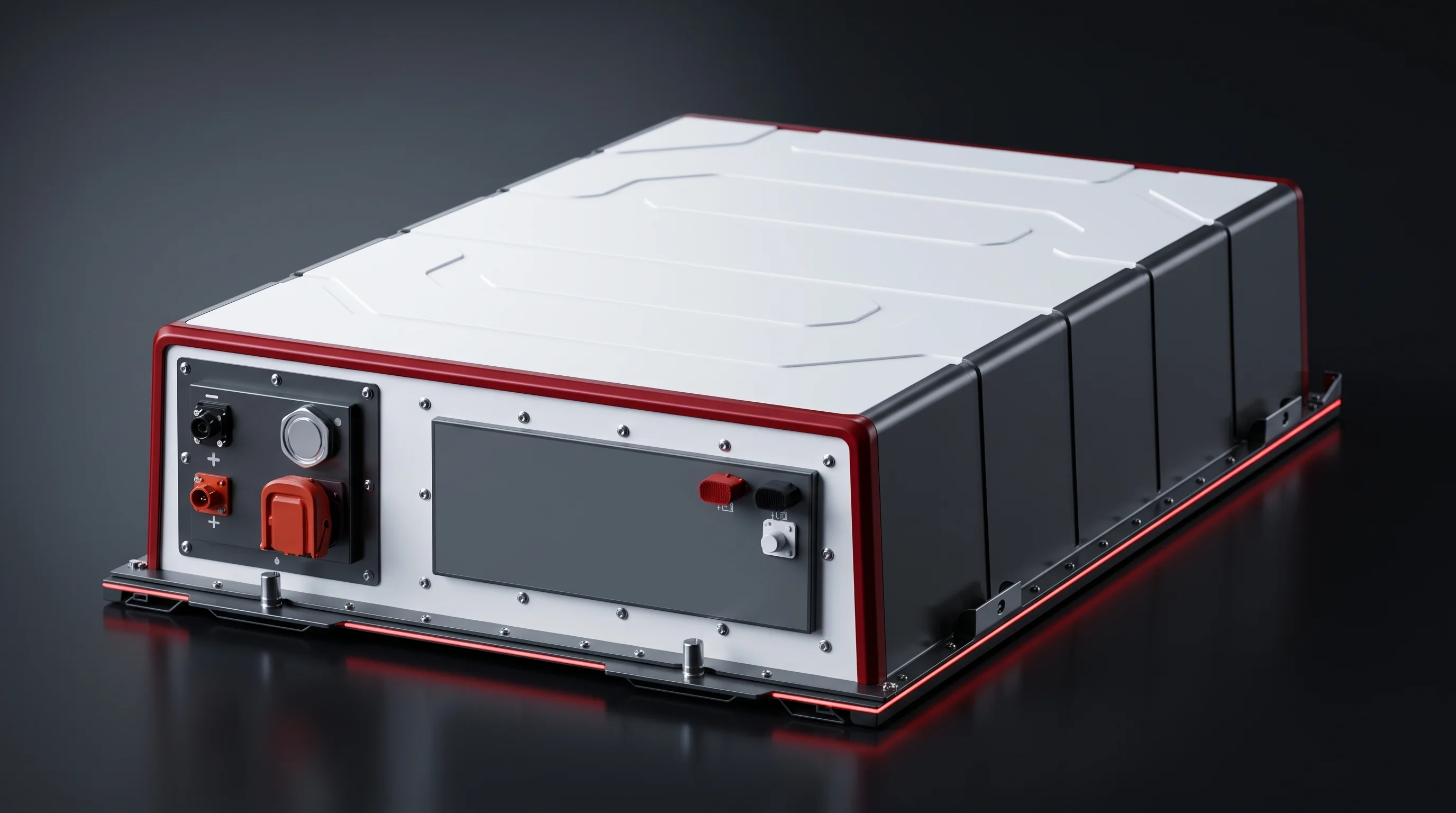
Conveyor figures, segment lengths, corner units and the RFID that carries the module number on the fixture are on the assembly conveyor system page.
Changeover
Tooling That Changes With Your Module
A different module inside the envelope does not re-plan this segment. The 17 stations stay in the same order; five of them carry the change.
Five stations carry the change
- 01Gripper and tray programThe BLP-UL robot picks a different cell footprint from a different tray layout.
- 08–09Press platens, locating fixtures and banding stopsThe largest single item: it sets both the stacking pitch and the pressed length.
- 11Re-taught, not re-tooledThe vision set learns the new terminal positions; no hardware changes.
- 13A different stored recipeCalled under the new busbar part number, created offline and pull tested first.
- 02No hardware at allThe grading window is a document both sides sign rather than a setting an operator types in.
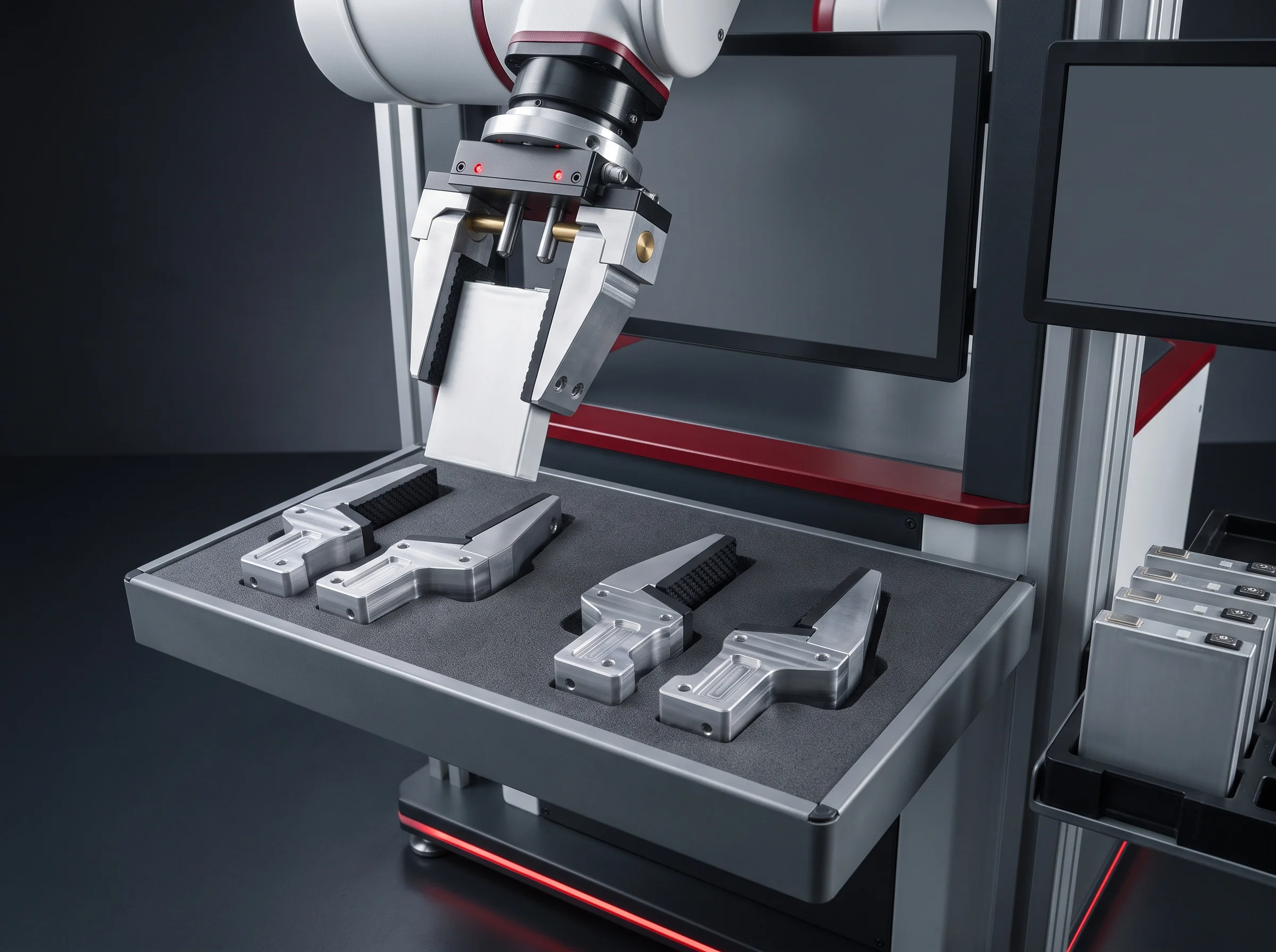
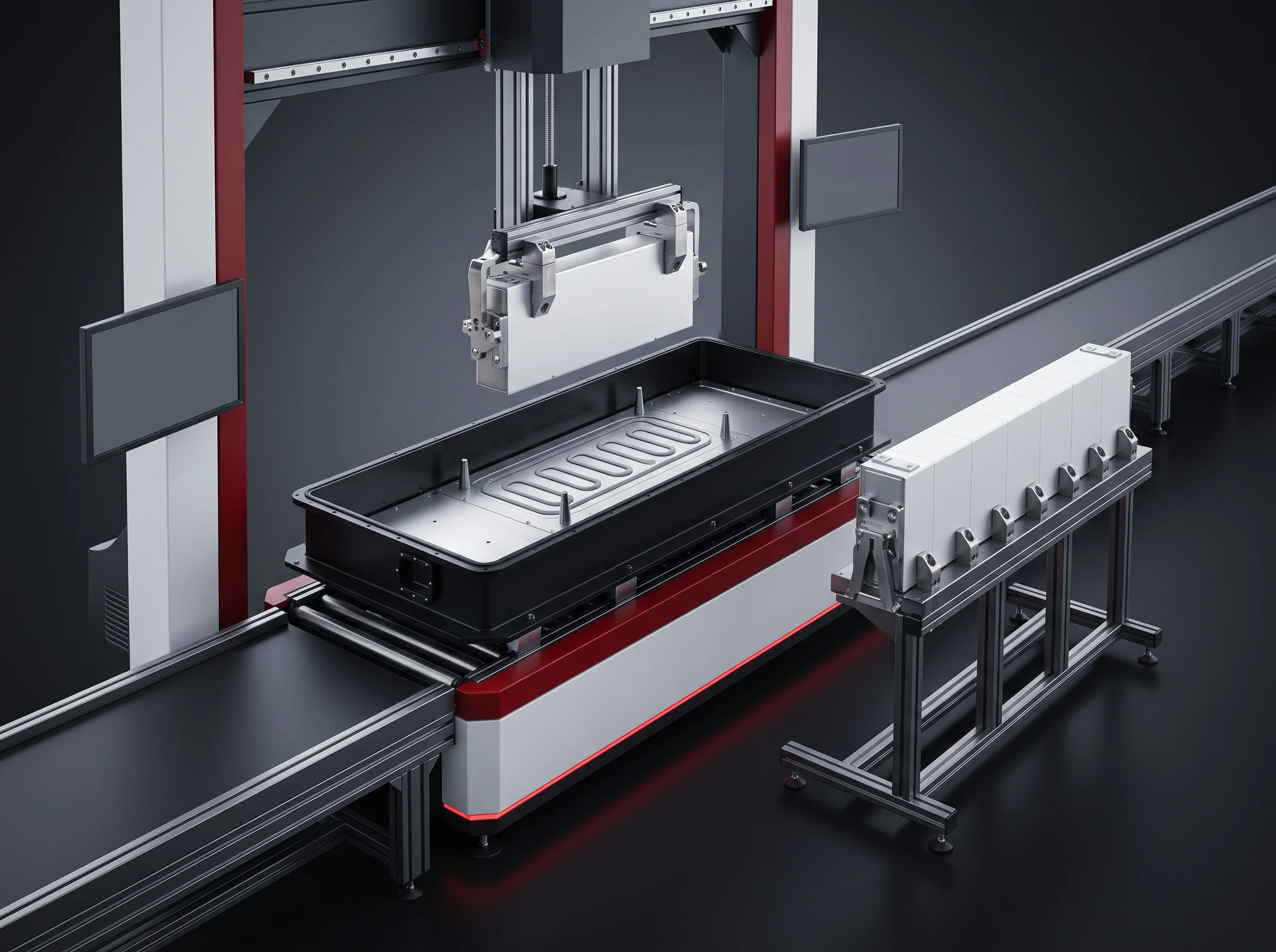
The hour-by-hour figures per station, what a first-time introduction of a new type adds, and how tooling is quoted per part number are on the cell compatibility and changeover page.
What to send
Send the Cell and Module Drawings
Six items are enough for the station list. Five of them are on documents you already hold.
- 01Cell datasheetFormat, dimensions, terminal layout and the grading you buy it at.
- 02Module drawingLength, width, height and the end plate form.
- 03Cells per module8 to 24 on the stacking frame; the blueprint is 13.
- 04Target takt or annual outputEither one; the other is derived and shown back to you.
- 05Bay dimensions with clear heightSo the layout is drawn into your building rather than onto a standard sheet.
- 06A sketch of what is on your floor nowOnly if this segment is joining a line you already run.
Returns within 24 hours
- The 17-station list with a level marked against each station on your tier.
- The tooling that comes off your module drawing, per part number.
- A layout drawn into your building, with the handover placed.
- A read on whether this is a station, a segment or a whole line.
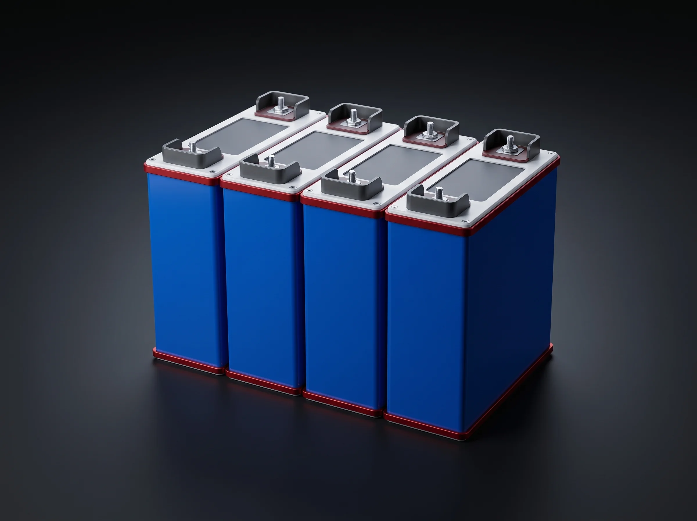
Still working out the tier? The takt bands, headcount and annual output per tier are on the capacity planning page, and the building side is on the factory layout and utilities page.
Signed before shipping
Battery Module Assembly Line Acceptance, Station by Station
Criteria are written by the process engineer who set the parameters and countersigned by quality, so the person judging the line is the person who set the number.
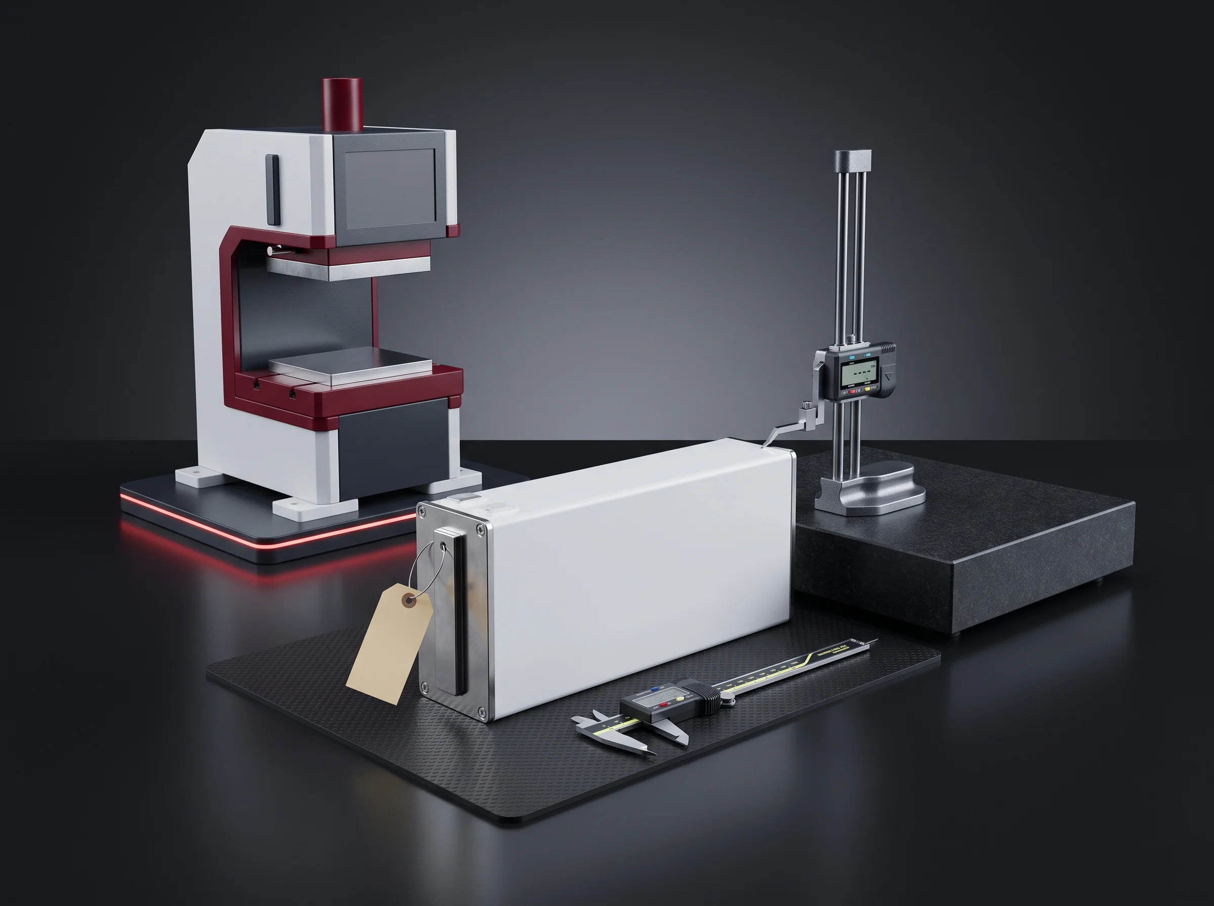
In the pre-assembly bay, on your own parts
- 20modulesSampled through the full item list
- 17stationsEach separately checkable
- 1baySegment powered in its ordered configuration
- Your cells, busbars, end plates and insulation sheets, not demonstration parts.
- The length distribution across the pressed batch shown in front of you.
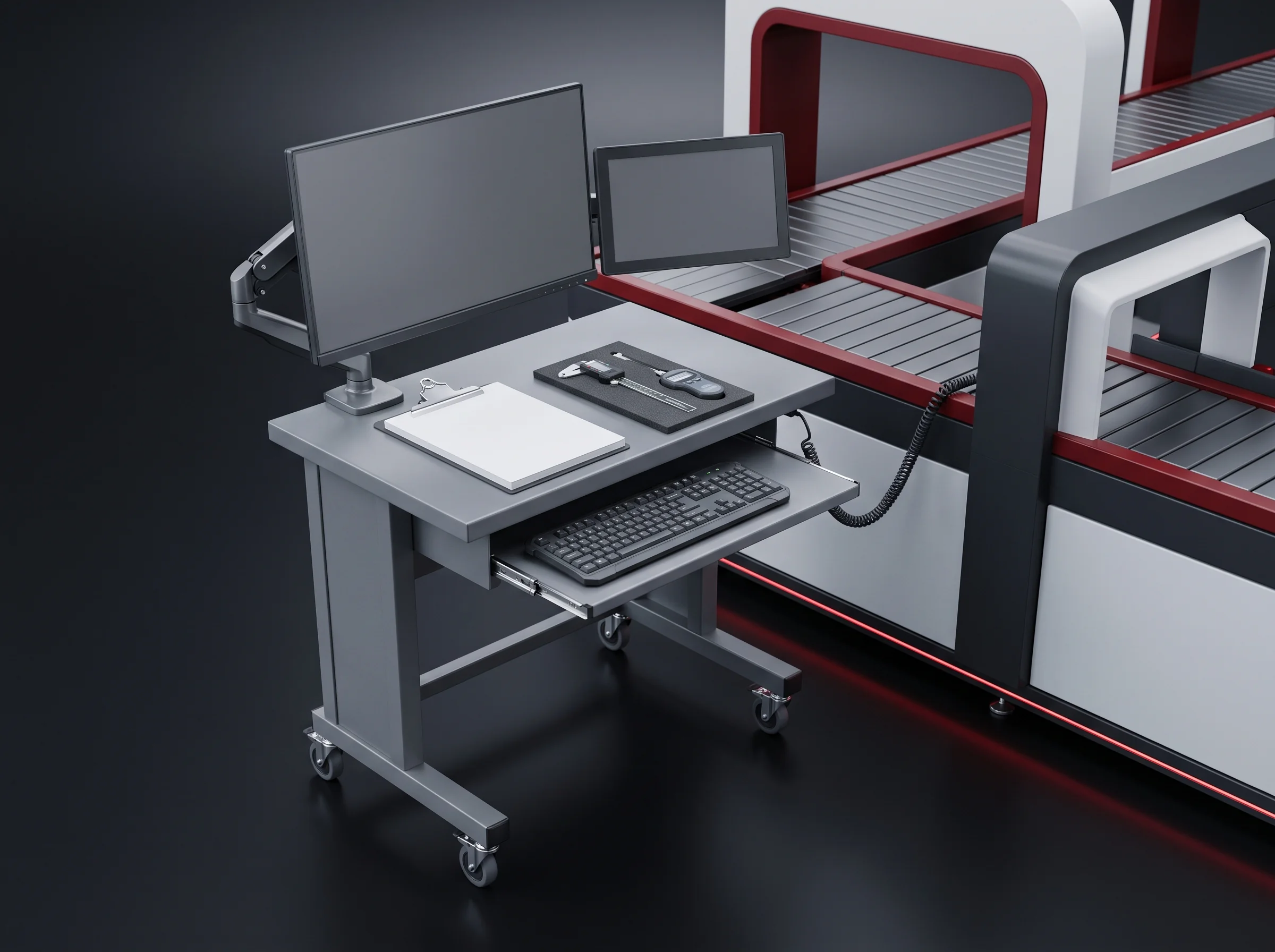
On your floor, after installation
- 8hContinuous at target takt, counted at station 01
- 99%Equipment-caused yield, human factors excluded in writing
- ≥1000NWeld coupons pull tested
- End-of-line testing run to the signed criteria on every module in the run.
- Both tiers accepted to the same list; only the levels beside each station differ.
Open items are closed by the engineer who owns the criterion
Open items are recorded line by line with the station, the measured value and the criterion beside each other. Only the open items are retested rather than the whole run.
Your enquiry, ready to send
If your email client opened, it is already in the message. If nothing opened, use one of the two routes below.
Talk to an engineer
Battery Module Assembly Line Enquiry
Send four things: your cell datasheet, your module drawing and configuration, your target takt or annual output, and a sketch of your floor if this segment joins a line you already run. The reply comes within 24 hours with the station list, the levels against your tier, and a read on whether this is a station, a segment or a whole line. More than 40 line segments have gone to plants in 12 countries under ISO 9001, CE and RoHS; wear parts ship within 48 hours. You can also start on the contact page.